ZHCS269C May   2011  – December 2016 CC110L

PRODUCTION DATA.  

  1. 1器件概述
    1. 1.1 特性
    2. 1.2 应用
    3. 1.3 说明
    4. 1.4 功能方框图
  2. 2修订历史记录
  3. 3Terminal Configuration and Functions
    1. 3.1 Pin Diagram
    2. 3.2 Signal Descriptions
  4. 4Specifications
    1. 4.1  Absolute Maximum Ratings
    2. 4.2  Handling Ratings
    3. 4.3  Recommended Operating Conditions
    4. 4.4  General Characteristics
    5. 4.5  Current Consumption
      1. 4.5.1 Typical TX Current Consumption over Temperature and Supply Voltage, 868 MHz
      2. 4.5.2 Typical TX Current Consumption over Temperature and Supply Voltage, 915 MHz
    6. 4.6  Typical RX Current Consumption Over Temperature and Input Power Level, 868 or 915 MHz
    7. 4.7  RF Receive Section
      1. 4.7.1 Typical Sensitivity over Temperature and Supply Voltage, 868 MHz, Sensitivity Optimized Setting
      2. 4.7.2 Typical Sensitivity over Temperature and Supply Voltage, 915 MHz, Sensitivity Optimized Setting
      3. 4.7.3 Blocking and Selectivity
    8. 4.8  RF Transmit Section
      1. 4.8.1 Typical Variation in Output Power over Temperature and Supply Voltage, 868 MHz
      2. 4.8.2 Typical Variation in Output Power over Temperature and Supply Voltage, 915 MHz
    9. 4.9  Crystal Oscillator
    10. 4.10 Frequency Synthesizer Characteristics
    11. 4.11 DC Characteristics
    12. 4.12 Power-On Reset
    13. 4.13 Thermal Characteristics
    14. 4.14 Typical Characteristics
      1. 4.14.1 Typical Characteristics, RX Current Consumption
      2. 4.14.2 Typical Characteristics, Blocking and Selectivity
  5. 5Detailed Description
    1. 5.1  Overview
    2. 5.2  Functional Block Diagram
    3. 5.3  Configuration Overview
    4. 5.4  Configuration Software
    5. 5.5  4-wire Serial Configuration and Data Interface
    6. 5.6  Chip Status Byte
    7. 5.7  Register Access
    8. 5.8  SPI Read
    9. 5.9  Command Strobes
    10. 5.10 FIFO Access
    11. 5.11 PATABLE Access
    12. 5.12 Microcontroller Interface and Pin Configuration
      1. 5.12.1 Configuration Interface
      2. 5.12.2 General Control and Status Pins
    13. 5.13 Data Rate Programming
    14. 5.14 Receiver Channel Filter Bandwidth
    15. 5.15 Demodulator, Symbol Synchronizer, and Data Decision
      1. 5.15.1 Frequency Offset Compensation
      2. 5.15.2 Bit Synchronization
      3. 5.15.3 Byte Synchronization
    16. 5.16 Packet Handling Hardware Support
      1. 5.16.1 Packet Format
        1. 5.16.1.1 Arbitrary Length Field Configuration
        2. 5.16.1.2 Packet Length > 255
      2. 5.16.2 Packet Filtering in Receive Mode
        1. 5.16.2.1 Address Filtering
        2. 5.16.2.2 Maximum Length Filtering
        3. 5.16.2.3 CRC Filtering
      3. 5.16.3 Packet Handling in Transmit Mode
      4. 5.16.4 Packet Handling in Receive Mode
      5. 5.16.5 Packet Handling in Firmware
    17. 5.17 Modulation Formats
      1. 5.17.1 Frequency Shift Keying
      2. 5.17.2 Amplitude Modulation
    18. 5.18 Received Signal Qualifiers and RSSI
      1. 5.18.1 Sync Word Qualifier
      2. 5.18.2 RSSI
      3. 5.18.3 Carrier Sense (CS)
        1. 5.18.3.1 CS Absolute Threshold
        2. 5.18.3.2 CS Relative Threshold
      4. 5.18.4 Clear Channel Assessment (CCA)
    19. 5.19 Radio Control
      1. 5.19.1 Power-On Start-Up Sequence
        1. 5.19.1.1 Automatic POR
        2. 5.19.1.2 Manual Reset
      2. 5.19.2 Crystal Control
      3. 5.19.3 Voltage Regulator Control
      4. 5.19.4 Active Modes (RX and TX)
      5. 5.19.5 RX Termination
      6. 5.19.6 Timing
        1. 5.19.6.1 Overall State Transition Times
        2. 5.19.6.2 Frequency Synthesizer Calibration Time
    20. 5.20 Data FIFO
    21. 5.21 Frequency Programming
    22. 5.22 VCO
      1. 5.22.1 VCO and PLL Self-Calibration
    23. 5.23 Voltage Regulators
    24. 5.24 Output Power Programming
    25. 5.25 General Purpose and Test Output Control Pins
    26. 5.26 Asynchronous and Synchronous Serial Operation
      1. 5.26.1 Asynchronous Serial Operation
      2. 5.26.2 Synchronous Serial Operation
    27. 5.27 System Considerations and Guidelines
      1. 5.27.1 SRD Regulations
      2. 5.27.2 Frequency Hopping and Multi-Channel Systems
      3. 5.27.3 Wideband Modulation when not Using Spread Spectrum
      4. 5.27.4 Data Burst Transmissions
      5. 5.27.5 Continuous Transmissions
      6. 5.27.6 Increasing Range
    28. 5.28 Configuration Registers
      1. 5.28.1 Configuration Register Details - Registers with preserved values in SLEEP state
      2. 5.28.2 Configuration Register Details - Registers that Loose Programming in SLEEP State
      3. 5.28.3 Status Register Details
    29. 5.29 Development Kit Ordering Information
  6. 6Applications, Implementation, and Layout
    1. 6.1 Bias Resistor
    2. 6.2 Balun and RF Matching
    3. 6.3 Crystal
    4. 6.4 Reference Signal
    5. 6.5 Additional Filtering
    6. 6.6 Power Supply Decoupling
    7. 6.7 PCB Layout Recommendations
  7. 7Device and Documentation Support
    1. 7.1 Device Support
      1. 7.1.1 Device Nomenclature
    2. 7.2 Documentation Support
      1. 7.2.1 Related Documentation from Texas Instruments
      2. 7.2.2 Community Resources
    3. 7.3 商标
    4. 7.4 静电放电警告
    5. 7.5 Export Control Notice
    6. 7.6 Glossary
    7. 7.7 Additional Acronyms
  8. 8Mechanical Packaging and Orderable Information
    1. 8.1 Packaging Information

封装选项

机械数据 (封装 | 引脚)
散热焊盘机械数据 (封装 | 引脚)
订购信息

器件概述

特性

  • 射频性能
    • 最高达 +12dBm 的可编程输出功率
    • 0.6kbps 时,接收灵敏度低至 −116dBm
    • 可编程数据速率:0.6kbps 至 600kbps
    • 频段:300-348MHz、387-464MHz
      和 779-928MHz
    • 支持 2-FSK、4-FSK、GFSK、MSK 和 OOK
  • 数字 特性
    • 灵活支持面向数据包的系统
    • 针对同步字插入、灵活数据包长度和自动 CRC 校验的片上支持
  • 低功耗 特性
    • 200nA 休眠模式电流消耗
    • 快速启动时间:仅需 240μs 即可从休眠模式进入 RX 或 TX 模式
    • 64 字节 RX 和 TX FIFO
  • 使用 CC1190 扩展范围
    • CC1190 是适用于 850-950MHz 的范围扩展器,
      堪称提升 CC110L 射频性能的理想之选
    • 高灵敏度
      • 1.2kBaud、868MHz、1% 误包率条件下为 -118dBm
      • 1.2kBaud、915MHz、1% 误包率条件下为 -120dBm
    • 频率为 868MHz 时,输出功率 +20dBm
    • 频率为 915MHz 时,输出功率 +26dBm
  • 常规说明
    • 外部组件更少;完全片上频率合成器,无需外部滤波器或射频开关
    • 绿色环保封装:符合 RoHS 要求,无锑无溴
    • 尺寸小(QLP 4mm x 4mm 封装,20 个引脚)
    • 适用于需要满足 EN 300 220(欧洲)和 FCC CFR 第 15 部分(美国)标准的系统
    • 支持异步和同步串行传输模式,向后兼容现有无线电通信协议

应用

  • 超低功耗无线 应用 (在 315MHz、433MHz、868MHz 和 915MHz ISM 或 SRD 频段下工作)
  • 无线警报和安全系统
  • 工业用监控和控制
  • 遥控
  • 玩具
  • 家庭和楼宇自动化

说明

CC110L 是一款成本优化型低于 1GHz 的射频收发器,适用于 300-348MHz、387-464MHz 和 779-928MHz 频段。电路基于热门的 CC1101 射频收发器,射频性能特性与之完全相同。将两个 CC110L 收发器配合使用可实现低成本双向射频链路。

射频收发器集成了高度可配置的基带调制解调器。调制解调器支持各种调制格式,具有高达 600kbps 的可配置数据速率。

CC110L 针对数据包处理、数据缓冲和脉冲传输提供广泛的硬件支持。

可以通过串行外设接口 (SPI) 对 CC110L 的主要操作参数和 64 位接收和发送 FIFO 进行控制。在典型系统中,CC110L 将与微控制器以及一些其他无源组件配合使用。
器件信息(1)

器件型号 封装 封装尺寸
CC110LRGP QFN (20) 4.00mm x 4.00mm
有关这些器件的更多信息,请参见Section 8,机械封装和可订购信息。

功能方框图

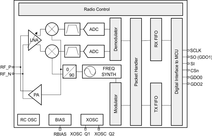
Figure 1-1 显示器件的功能方框图。

CC110L CC110L_simp_bd_swrs109.gif Figure 1-1 功能框图