ZHCSKH8C December 2009 – December 2019 BQ24072T , BQ24075T , BQ24079T
PRODUCTION DATA.
- 1 特性
- 2 应用
- 3 说明
- 4 修订历史记录
- 5 说明 (续)
- 6 Device Options
- 7 Pin Configuration and Functions
- 8 Specifications
-
9 Detailed Description
- 9.1 Overview
- 9.2 Functional Block Diagram
- 9.3
Feature Description
- 9.3.1 Undervoltage Lockout (UVLO)
- 9.3.2 Overvoltage Protection (OVP)
- 9.3.3 Dynamic Power-Path Management
- 9.3.4 Battery Charging
- 9.3.5 Charge Current Translator
- 9.3.6 Battery Detection and Recharge
- 9.3.7 Termination Disable (TD Input, BQ24072T)
- 9.3.8 Battery Disconnect (SYSOFF Input)
- 9.3.9 Dynamic Charge Timers (TMR Input)
- 9.3.10 Status Indicators (PGOOD, CHG)
- 9.3.11 Thermal Regulation and Thermal Shutdown
- 9.3.12 Battery Pack Temperature Monitoring
- 9.4 Device Functional Modes
-
10Applications and Implementation
- 10.1 Application Information
- 10.2
Typical Applications
- 10.2.1
Using the BQ24075T, BQ24079T to Disconnect the Battery from the System
- 10.2.1.1 Design Requirements
- 10.2.1.2
Detailed Design Procedure
- 10.2.1.2.1 Program the Fast Charge Current (ISET):
- 10.2.1.2.2 Program the Input Current Limit (ILIM):
- 10.2.1.2.3 Program 6.25-hour Fast-Charge Safety Timer (TMR):
- 10.2.1.2.4 TS Function:
- 10.2.1.2.5 CHG and PGOOD LED Status:
- 10.2.1.2.6 Processor Monitoring Status:
- 10.2.1.2.7 System ON/OFF (SYSOFF):
- 10.2.1.2.8 Selecting IN, OUT and BAT Capacitors
- 10.2.1.3 Application Curves
- 10.2.2 BQ24072T in a Host Controlled Charger Application
- 10.2.1
Using the BQ24075T, BQ24079T to Disconnect the Battery from the System
- 11Power Supply Recommendations
- 12Layout
- 13器件和文档支持
- 14机械、封装和可订购信息
9.3.12 Battery Pack Temperature Monitoring
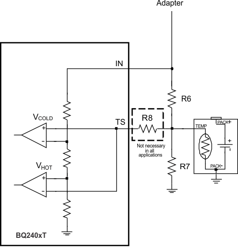
The BQ2407xT features an external battery pack temperature monitoring input. The TS input connects to the NTC thermistor in the battery pack to monitor battery temperature and prevent dangerous over-temperature conditions. During charging, the voltage at TS is continuously monitored. If, at any time, the voltage at TS is outside of the operating range (VCOLD to VHOT), charging is suspended. The timers maintain their values but suspend counting. When the voltage measured at TS returns to within the operation window, charging is resumed and the timers continue counting. When charging is suspended due to a battery pack temperature fault, the CHG output remains low and continues to indicate charging.


Where:
VCOLD = 0.25 X VIN
VHOT = 0.125 X VIN
RHOT is the expected thermistor resistance at the programmed hot threshold, RCOLD is the expected thermistor resistance at the programmed cold threshold. If the value of R6 is less than 100 kΩ, R8 must be added to protect the IC from 28V inputs. If R6 is greater than 100 kΩ, R8 does not need to be used.
 Figure 18. NTC Monitoring Function
 For applications that do not require the TS monitoring function, set R6 = 200 kΩ and R7 = 49.9 kΩ to set the TS voltage at a valid level and maintain charging.