ZHCSID7 June   2018 ADS8688AT

PRODUCTION DATA.  

  1. 特性
  2. 应用
  3. 说明
  4. 修订历史记录
  5. Pin Configuration and Functions
    1.     Pin Functions
  6. Specifications
    1. 6.1 Absolute Maximum Ratings
    2. 6.2 ESD Ratings
    3. 6.3 Recommended Operating Conditions
    4. 6.4 Thermal Information
    5. 6.5 Electrical Characteristics
    6. 6.6 Timing Requirements: Serial Interface
    7. 6.7 Switching Characteristics: Serial Interface
    8. 6.8 Typical Characteristics
  7. Detailed Description
    1. 7.1 Overview
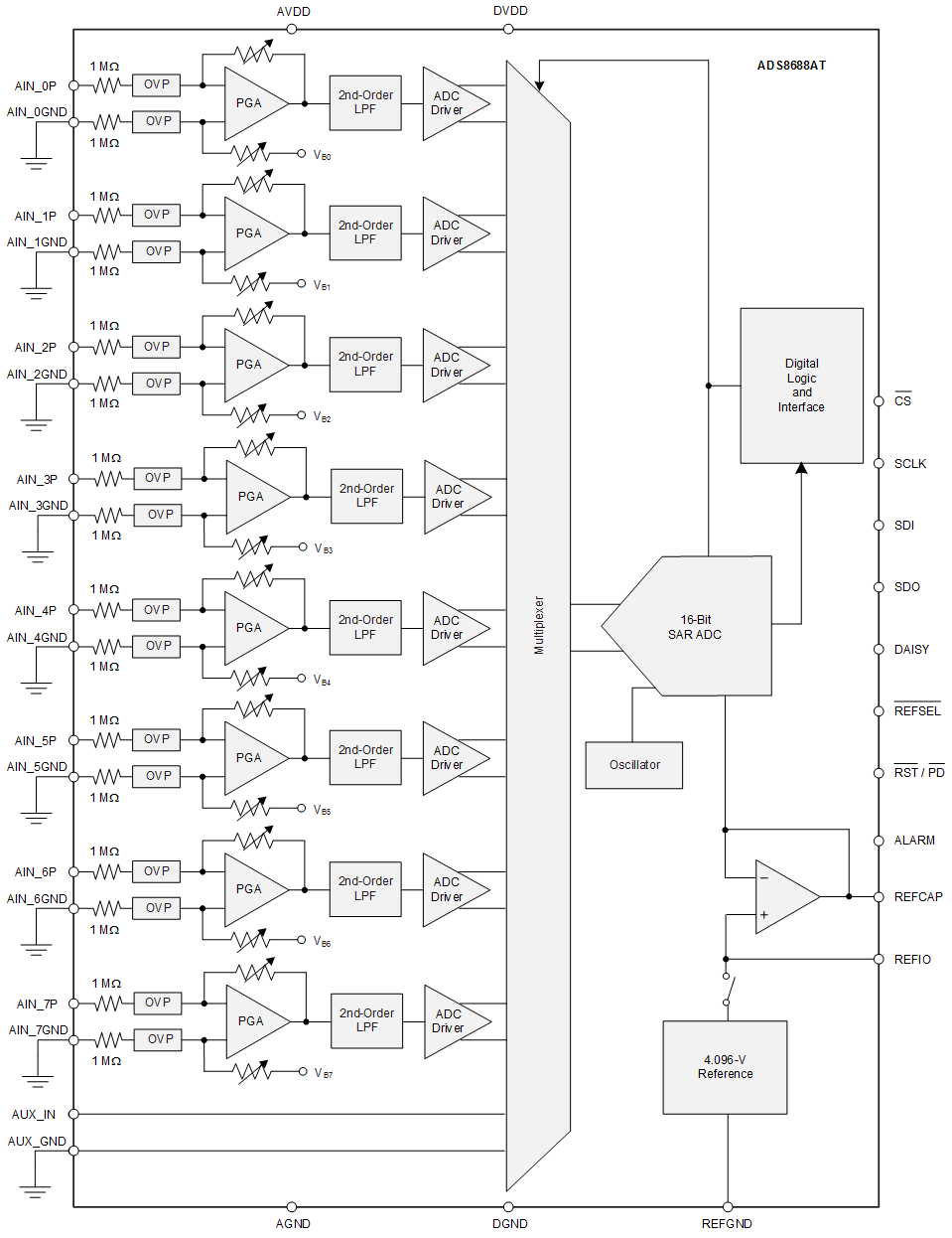
    2. 7.2 Functional Block Diagram
    3. 7.3 Feature Description
      1. 7.3.1  Analog Inputs
      2. 7.3.2  Analog Input Impedance
      3. 7.3.3  Input Overvoltage Protection Circuit
      4. 7.3.4  Programmable Gain Amplifier (PGA)
      5. 7.3.5  Second-Order, Low-Pass Filter (LPF)
      6. 7.3.6  ADC Driver
      7. 7.3.7  Multiplexer (MUX)
      8. 7.3.8  Reference
        1. 7.3.8.1 Internal Reference
        2. 7.3.8.2 External Reference
      9. 7.3.9  Auxiliary Channel
        1. 7.3.9.1 Input Driver for the AUX Channel
      10. 7.3.10 ADC Transfer Function
      11. 7.3.11 Alarm Feature
    4. 7.4 Device Functional Modes
      1. 7.4.1 Device Interface
        1. 7.4.1.1 Digital Pin Description
          1. 7.4.1.1.1 CS (Input)
          2. 7.4.1.1.2 SCLK (Input)
          3. 7.4.1.1.3 SDI (Input)
          4. 7.4.1.1.4 SDO (Output)
          5. 7.4.1.1.5 DAISY (Input)
          6. 7.4.1.1.6 RST/PD (Input)
        2. 7.4.1.2 Data Acquisition Example
        3. 7.4.1.3 Host-to-Device Connection Topologies
          1. 7.4.1.3.1 Daisy-Chain Topology
          2. 7.4.1.3.2 Star Topology
      2. 7.4.2 Device Modes
        1. 7.4.2.1 Continued Operation in the Selected Mode (NO_OP)
        2. 7.4.2.2 Frame Abort Condition (FRAME_ABORT)
        3. 7.4.2.3 STANDBY Mode (STDBY)
        4. 7.4.2.4 Power-Down Mode (PWR_DN)
        5. 7.4.2.5 Auto Channel Enable With Reset (AUTO_RST)
        6. 7.4.2.6 Manual Channel n Select (MAN_Ch_n)
        7. 7.4.2.7 Channel Sequencing Modes
        8. 7.4.2.8 Reset Program Registers (RST)
    5. 7.5 Register Maps
      1. 7.5.1 Command Register Description
      2. 7.5.2 Program Register Description
        1. 7.5.2.1 Program Register Read/Write Operation
        2. 7.5.2.2 Program Register Map
        3. 7.5.2.3 Program Register Descriptions
          1. 7.5.2.3.1 Auto-Scan Sequencing Control Registers
            1. 7.5.2.3.1.1 Auto-Scan Sequence Enable Register (address = 01h)
              1. Table 11. AUTO_SEQ_EN Field Descriptions
            2. 7.5.2.3.1.2 Channel Power Down Register (address = 02h)
              1. Table 12. Channel Power Down Register Field Descriptions
          2. 7.5.2.3.2 Device Features Selection Control Register (address = 03h)
            1. Table 13. Feature Select Register Field Descriptions
          3. 7.5.2.3.3 Range Select Registers (addresses 05h-0Ch)
            1. Table 16. Channel n Input Range Registers Field Descriptions
          4. 7.5.2.3.4 Alarm Flag Registers (Read-Only)
            1. 7.5.2.3.4.1 ALARM Overview Tripped-Flag Register (address = 10h)
              1. Table 17. ALARM Overview Tripped-Flag Register Field Descriptions
            2. 7.5.2.3.4.2 Alarm Flag Registers: Tripped and Active (address = 11h to 14h)
              1. Table 18. ALARM Ch0-3 Tripped-Flag Register Field Descriptions
              2. Table 19. ALARM Ch0-3 Active-Flag Register Field Descriptions
              3. Table 20. ALARM Ch4-7 Tripped-Flag Register Field Descriptions
              4. Table 21. ALARM Ch4-7 Active-Flag Register Field Descriptions
          5. 7.5.2.3.5 Alarm Threshold Setting Registers
            1. Table 22. Channel n Hysteresis Register Field Descriptions (n = 0 to 7)
            2. Table 23. Channel n High Threshold MSB Register Field Descriptions (n = 0 to 7)
            3. Table 24. Channel n High Threshold LSB Register Field Descriptions (n = 0 to 7)
            4. Table 25. Channel n Low Threshold MSB Register Field Descriptions (n = 0 to 7)
            5. Table 26. Channel n Low Threshold MSB Register Field Descriptions (n = 0 to 7)
          6. 7.5.2.3.6 Command Read-Back Register (address = 3Fh)
            1. Table 27. Command Read-Back Register Field Descriptions
  8. Application and Implementation
    1. 8.1 Application Information
    2. 8.2 Typical Applications
      1. 8.2.1 Phase-Compensated, 8-Channel, Multiplexed Data Acquisition System for Power Automation
        1. 8.2.1.1 Design Requirements
        2. 8.2.1.2 Detailed Design Procedure
        3. 8.2.1.3 Application Curve
      2. 8.2.2 16-Bit, 8-Channel, Integrated Analog Input Module for Programmable Logic Controllers (PLCs)
        1. 8.2.2.1 Design Requirements
        2. 8.2.2.2 Detailed Design Procedure
        3. 8.2.2.3 Application Curve
  9. Power Supply Recommendations
  10. 10Layout
    1. 10.1 Layout Guidelines
    2. 10.2 Layout Example
  11. 11器件和文档支持
    1. 11.1 文档支持
      1. 11.1.1 相关文档
    2. 11.2 接收文档更新通知
    3. 11.3 社区资源
    4. 11.4 商标
    5. 11.5 静电放电警告
    6. 11.6 术语表
  12. 12机械、封装和可订购信息

封装选项

机械数据 (封装 | 引脚)
散热焊盘机械数据 (封装 | 引脚)
订购信息

特性

  • 具有集成模拟前端的 16 位 ADC
  • 和 8 通道多路复用器,支持自动和手动扫描
  • 通道独立的可编程输入:
    • ±10.24V、±5.12V、±2.56V、±1.28V、±0.64V
    • 10.24V、5.12V、2.56V、1.28 V
  • 5V 模拟电源:1.65V 到 5V I/O 电源
  • 恒定的阻性输入阻抗:1MΩ
  • 输入过压保护:高达 ±20V
  • 集成 4.096V 基准电压,温漂为 6ppm/°C
  • 出色的性能:
    • 500kSPS 的总吞吐量
    • 差分非线性 (DNL):±0.5 最低有效位 (LSB);最大积分非线性 (INL):±0.75 LSB
    • 增益误差和失调电压的温漂为 1ppm/°C
    • SNR:92dB;THD:–102dB
    • 低功耗:65mW
  • AUX 输入 → 直接连接到 ADC 输入
  • ALARM → 每通道的高低阈值
  • SPI™兼容接口,支持菊链式连接
  • 温度范围:–55°C 至 +125°C
  • TSSOP-38 封装 (9.7mm × 4.4mm)
  • 框图

    ADS8688AT frontpage_ads8688AT_sbas813.gif