ZHCSIS8F September 2018 – March 2024 TPS7H2201-SEP , TPS7H2201-SP
PRODUCTION DATA
- 1
- 1 特性
- 2 应用
- 3 说明
- 4 Device Options
- 5 Pin Configuration and Functions
-
6 Specifications
- 6.1 Absolute Maximum Ratings
- 6.2 ESD Ratings
- 6.3 Recommended Operating Conditions
- 6.4 Thermal Information
- 6.5 Electrical Characteristics: All Devices
- 6.6 Electrical Characteristics: CFP and KGD Options
- 6.7 Electrical Characteristics: HTSSOP Option
- 6.8 Switching Characteristics (All Devices)
- 6.9 Quality Conformance Inspection
- 6.10 Typical Characteristics
- 7 Parameter Measurement Information
- 8 Detailed Description
- 9 Application and Implementation
- 10Device and Documentation Support
- 11Revision History
- 12Mechanical, Packaging, and Orderable Information
7 Parameter Measurement Information
 Figure 7-1 EN Signal Low Time to Restart
Device (tLOW)
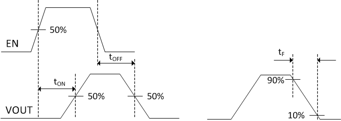
 Figure 7-2 Turn-On
(tON), Turn-Off (tOFF) and VOUT Fall Time
(tF) Waveforms
 Figure 7-3 OVP Assert
(tASSERT) and OVP Deassert (tDEASSERT) Waveforms
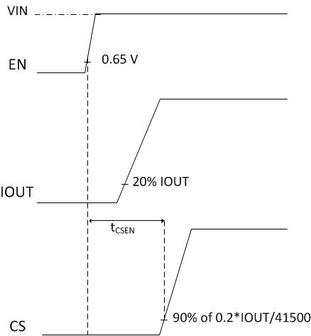
 Figure 7-4 tCSEN
Waveforms
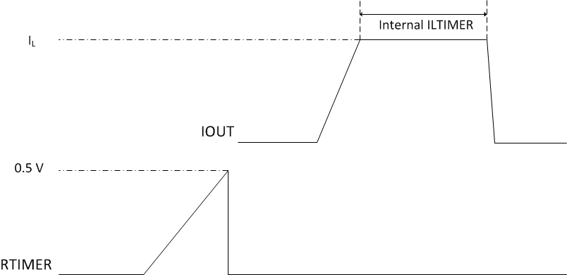
 Figure 7-5 Internal ILTIMER
Waveforms
 Figure 7-6 VOUT Current to CS Change
Delay Time