• Menu
  • Product
  • Email
  • PDF
  • Order now
  • MSP432E411Y SimpleLink™ 以太网微控制器

    • ZHCSH08 October   2017 MSP432E411Y

      PRODUCTION DATA.  

  • CONTENTS
  • SEARCH
  • MSP432E411Y SimpleLink™ 以太网微控制器
  1. 1器件概述
    1. 1.1 特性
    2. 1.2 应用
    3. 1.3 说明
    4. 1.4 功能框图
  2. 2Revision History
  3. 3Device Characteristics
    1. 3.1 Related Products
  4. 4Terminal Configuration and Functions
    1. 4.1 Pin Diagram
    2. 4.2 Pin Attributes
    3. 4.3 Signal Descriptions
      1. Table 4-3 Signal Descriptions
    4. 4.4 GPIO Pin Multiplexing
    5. 4.5 Buffer Type
    6. 4.6 Connections for Unused Pins
  5. 5Specifications
    1. 5.1  Absolute Maximum Ratings
    2. 5.2  ESD Ratings
    3. 5.3  Recommended Operating Conditions
    4. 5.4  Recommended DC Operating Conditions
    5. 5.5  Recommended GPIO Operating Characteristics
    6. 5.6  Recommended Fast GPIO Pad Operating Conditions
    7. 5.7  Recommended Slow GPIO Pad Operating Conditions
    8. 5.8  GPIO Current Restrictions
    9. 5.9  I/O Reliability
    10. 5.10 Current Consumption
    11. 5.11 Peripheral Current Consumption
    12. 5.12 LDO Regulator Characteristics
    13. 5.13 Power Dissipation
    14. 5.14 Thermal Resistance Characteristics, 212-Pin ZAD (NFBGA) Package
    15. 5.15 Timing and Switching Characteristics
      1. 5.15.1  Load Conditions
      2. 5.15.2  Power Supply Sequencing
        1. 5.15.2.1 Power and Brownout
          1. Table 5-3 Power and Brownout Levels
          2. 5.15.2.1.1 VDDA Levels
          3. 5.15.2.1.2 VDD Levels
          4. 5.15.2.1.3 VDDC Levels
          5. 5.15.2.1.4 VDD Glitch Response
          6. 5.15.2.1.5 VDD Droop Response
      3. 5.15.3  Reset Timing
        1. Table 5-4 Reset Characteristics
      4. 5.15.4  Clock Specifications
        1. 5.15.4.1 PLL Specifications
          1. Table 5-5 Phase Locked Loop (PLL) Characteristics
          2. 5.15.4.1.1 PLL Configuration
        2. 5.15.4.2 PIOSC Specifications
        3. 5.15.4.3 Low-Frequency Oscillator Specifications
          1. Table 5-9 Low-Frequency Oscillator Characteristics
        4. 5.15.4.4 Hibernation Low-Frequency Oscillator Specifications
          1. Table 5-10 Hibernation External Oscillator (XOSC) Input Characteristics
          2. Table 5-11 Hibernation Internal Low-Frequency Oscillator Clock Characteristics
        5. 5.15.4.5 Main Oscillator Specifications
          1. Table 5-12 Main Oscillator Input Characteristics
        6. 5.15.4.6 Main Oscillator Specification WIth ADC
          1. Table 5-14 System Clock Characteristics With ADC Operation
        7. 5.15.4.7 System Clock Characteristics With USB Operation
          1. Table 5-15 System Clock Characteristics With USB Operation
      5. 5.15.5  Sleep Modes
        1. Table 5-16 Wake From Sleep Characteristics
        2. Table 5-17 Wake From Deep Sleep Characteristics
      6. 5.15.6  Hibernation Module
        1. Table 5-18 Hibernation Module Battery Characteristics
        2. Table 5-19 Hibernation Module Characteristics
        3. Table 5-20 Hibernation Module Tamper I/O Characteristics
      7. 5.15.7  Flash Memory
        1. Table 5-21 Flash Memory Characteristics
      8. 5.15.8  EEPROM
        1. Table 5-22 EEPROM Characteristics
      9. 5.15.9  Input/Output Pin Characteristics
        1. Table 5-23 Fast GPIO Module Characteristics
        2. Table 5-24 Slow GPIO Module Characteristics
        3. 5.15.9.1    Types of I/O Pins and ESD Protection
          1. 5.15.9.1.1 Hibernate WAKE pin
            1. Table 5-25 Pad Voltage and Current Characteristics for Hibernate WAKE Pin
          2. 5.15.9.1.2 Nonpower I/O Pins
            1. Table 5-26 Nonpower I/O Pad Voltage and Current Characteristics
      10. 5.15.10 External Peripheral Interface (EPI)
        1. Table 5-28 EPI SDRAM Characteristics
        2. Table 5-29 EPI SDRAM Interface Characteristics
        3. Table 5-30 EPI Host-Bus 8 and Host-Bus 16 Interface Characteristics
        4. Table 5-31 EPI General-Purpose Interface Characteristics
        5. Table 5-32 EPI PSRAM Interface Characteristics
      11. 5.15.11 Analog-to-Digital Converter (ADC)
        1. Table 5-33 Electrical Characteristics for ADC at 1 Msps
        2. Table 5-34 Electrical Characteristics for ADC at 2 Msps
      12. 5.15.12 Synchronous Serial Interface (SSI)
        1. Table 5-35 SSI Characteristics
        2. Table 5-36 Bi- and Quad-SSI Characteristics
      13. 5.15.13 Inter-Integrated Circuit (I2C) Interface
        1. Table 5-37 I2C Characteristics
      14. 5.15.14 Ethernet Controller
        1. 5.15.14.1 DC Characteristics
          1. Table 5-38 Ethernet PHY DC Characteristics
        2. 5.15.14.2 Clock Characteristics for Ethernet
          1. Table 5-39 MOSC 25-MHz Crystal Specification
          2. Table 5-40 MOSC Single-Ended 25-MHz Oscillator Specification
          3. Table 5-41 EN0RREF_CLK 50-MHz Oscillator Specification
        3. 5.15.14.3 AC Characteristics
          1. Table 5-42 Ethernet Controller Enable and Software Reset Timing
          2. Table 5-43 MII Serial Management Timing
          3. Table 5-44 100-Mbps MII Transmit Timing
          4. Table 5-45 100-Mbps MII Receive Timing
          5. Table 5-46 100Base-TX Transmit Timing
          6. Table 5-47 10-Mbps MII Transmit Timing
          7. Table 5-48 10-Mbps MII Receive Timing
          8. Table 5-49 10Base-T Normal Link Pulse Timing
          9. Table 5-50 Auto-Negotiation Fast Link Pulse (FLP) Timing
          10. Table 5-51 100Base-TX Signal Detect Timing
          11. Table 5-52 RMII Transmit Timing
          12. Table 5-53 RMII Receive Timing
      15. 5.15.15 Universal Serial Bus (USB) Controller
        1. Table 5-54 ULPI Interface Timing
      16. 5.15.16 LCD Controller
        1. Table 5-55 LCD Controller Load Capacitance Limits
        2. 5.15.16.1   LCD Interface Display Driver (LIDD Mode)
          1. Table 5-56 LCD Switching Characteristics
          2. Table 5-57 Timing Requirements for LCDDATA in LIDD Mode
          3. 5.15.16.1.1 Hitachi Mode
          4. 5.15.16.1.2 Motorola 6800 Mode
          5. 5.15.16.1.3 Intel 8080 Mode
        3. 5.15.16.2   LCD Raster Mode
          1. Table 5-58 Switching Characteristics for LCD Raster Mode
      17. 5.15.17 Analog Comparator
        1. Table 5-59 Analog Comparator Characteristics
        2. Table 5-60 Analog Comparator Characteristics
        3. Table 5-61 Analog Comparator Voltage Reference Characteristics
        4. Table 5-62 Analog Comparator Voltage Reference Characteristics
      18. 5.15.18 Pulse-Width Modulator (PWM)
        1. Table 5-63 PWM Timing Characteristics
      19. 5.15.19 Emulation and Debug
        1. Table 5-64 JTAG Characteristics
  6. 6Detailed Description
    1. 6.1 Overview
    2. 6.2 Functional Block Diagram
    3. 6.3 Arm Cortex-M4F Processor Core
      1. 6.3.1 Processor Core
      2. 6.3.2 System Timer (SysTick)
      3. 6.3.3 Nested Vectored Interrupt Controller (NVIC)
      4. 6.3.4 System Control Block (SCB)
      5. 6.3.5 Memory Protection Unit (MPU)
      6. 6.3.6 Floating-Point Unit (FPU)
    4. 6.4 On-Chip Memory
      1. 6.4.1 SRAM
      2. 6.4.2 Flash Memory
      3. 6.4.3 ROM
      4. 6.4.4 EEPROM
      5. 6.4.5 Memory Map
    5. 6.5 Peripherals
      1. 6.5.1  External Peripheral Interface (EPI)
      2. 6.5.2  Cyclical Redundancy Check (CRC)
      3. 6.5.3  Advanced Encryption Standard (AES) Accelerator
      4. 6.5.4  Data Encryption Standard (DES) Accelerator
      5. 6.5.5  Secure Hash Algorithm/Message Digest Algorithm (SHA/MD5) Accelerator
      6. 6.5.6  Serial Communications Peripherals
        1. 6.5.6.1 Ethernet MAC and PHY
        2. 6.5.6.2 Controller Area Network (CAN)
        3. 6.5.6.3 Universal Serial Bus (USB)
        4. 6.5.6.4 Universal Asynchronous Receiver/Transmitter (UART)
        5. 6.5.6.5 1-Wire Master Module
        6. 6.5.6.6 Inter-Integrated Circuit (I2C)
        7. 6.5.6.7 Quad Synchronous Serial Interface (QSSI)
      7. 6.5.7  System Integration
        1. 6.5.7.1 Direct Memory Access (DMA)
        2. 6.5.7.2 System Control and Clocks
        3. 6.5.7.3 Programmable Timers
        4. 6.5.7.4 Capture Compare PWM (CCP) Pins
        5. 6.5.7.5 Hibernation (HIB) Module
        6. 6.5.7.6 Watchdog Timers
        7. 6.5.7.7 Programmable GPIOs
      8. 6.5.8  LCD Controller
      9. 6.5.9  Advanced Motion Control
        1. 6.5.9.1 Pulse Width Modulation (PWM)
        2. 6.5.9.2 Quadrature Encoder With Index (QEI) Module
      10. 6.5.10 Analog
        1. 6.5.10.1 ADC
        2. 6.5.10.2 Analog Comparators
      11. 6.5.11 JTAG and Arm Serial Wire Debug
      12. 6.5.12 Peripheral Memory Map
    6. 6.6 Identification
    7. 6.7 Boot Modes
  7. 7Applications, Implementation, and Layout
    1. 7.1 System Design Guidelines
  8. 8器件和文档支持
    1. 8.1 入门和后续步骤
    2. 8.2 器件命名规则
    3. 8.3 工具和软件
    4. 8.4 文档支持
    5. 8.5 Community Resources
    6. 8.6 商标
    7. 8.7 静电放电警告
    8. 8.8 出口管制提示
    9. 8.9 术语表
  9. 9机械、封装和可订购信息
  10. 重要声明
search No matches found.
  • Full reading width
    • Full reading width
    • Comfortable reading width
    • Expanded reading width
  • Card for each section
  • Card with all content


DATA SHEET

MSP432E411Y SimpleLink™ 以太网微控制器

本资源的原文使用英文撰写。 为方便起见,TI 提供了译文;由于翻译过程中可能使用了自动化工具,TI 不保证译文的准确性。 为确认准确性,请务必访问 ti.com 参考最新的英文版本(控制文档)。

1 器件概述

1.1 特性

  • 内核
    • 120MHz ARM®Cortex®- 具有浮点运算单元 (FPU) 的 M4F 处理器内核
  • 连接
    • 以太网 MAC:10/100 以太网 MAC 带媒体独立接口 (MII) 和简化媒体独立接口 (RMII)
    • 以太网 PHY:具有 IEEE 1588 PTP 硬件支持的 PHY
    • 通用串行总线 (USB):具有 ULPI 接口选项和链路层电源管理 (LPM) 的 USB 2.0 OTG、主机或器件
    • 8 个通用异步接收器/发射器 (UART),每个具有独立计时的发送器和接收器
    • 4 个四通道同步串行接口 (QSSI):提供双通道、四通道和高级 SSI 支持
    • 提供高速模式支持的 10 个内部集成电路 (I2C) 模块
    • 2 个 CAN 2.0 A 和 B 控制器:多播共享串行总线标准
    • 1 个具有双向串行通信协议的单线制模块通过一条单线提供电源和数据
  • 存储器
    • 具有 4 个存储体的 1024KB 闪存存储器配置支持对每个存储体提供独立代码保护
    • 具有单周期访问的 256KB SRAM 以 120MHz 时钟频率提供近 2GB/s 的内存带宽
    • 6KB EEPROM:每 2 个页块写入 500k、矫正、锁定保护
    • 内部 ROM:搭载有 SimpleLink™SDK 软件
      • 外设驱动程序库
      • 引导加载程序
    • 外部外设接口 (EPI):8、16 或 32 位专用并行接口访问外部器件和存储器(SDRAM、闪存或 SRAM)
  • 安全性
    • 高级加密标准 (AES):基于 128、192 和 256 位密钥的硬件加速数据加密和解密
    • 数据加密标准 (DES):具有 168 位有效密钥长度并且支持块密码实施的硬件加速数据加密和解密
    • 安全哈希算法/消息摘要算法 (SHA/MD5):支持 SHA-1、SHA-2 和 MD5 哈希计算的高级哈希引擎
    • 循环冗余校验 (CRC) 硬件
    • 篡改:支持四个篡改输入和可配置篡改事件响应
  • 模拟
    • 2 个基于 12 位 SAR 的 ADC 模块,每个模块支持高达 200 万次/秒的采样率 (2Msps)
    • 3 个独立的模拟比较器控制器
    • 16 个数字比较器
  • 系统管理
    • JTAG 和串行线调试 (SWD):一个具有集成 ARM SWD 的 JTAG 模块提供访问和控制测试设计 特性 的途径,如 I/O 引脚监督和控制、扫描测试和调试。
  • 开发套件和软件(请参阅 工具和软件)
    • SimpleLink™MSP-EXP432E401Y LaunchPad™开发套件
    • SimpleLink MSP432E4 软件开发套件 (SDK)
  • 封装信息
    • 封装:212 焊球 NFBGA (ZAD)
    • 扩展工作温度(环境)范围:–40°C 至 105°C

1.2 应用

  • 工业以太网网关
  • 工业智能网关
  • 适用于楼宇自动化的区域控制器
  • 工厂自动化数据收集器和网关
  • 面向电网基础设施的数据集中器
  • 无线转以太网网关

1.3 说明

SimpleLink MSP432E411Y ARM®Cortex®-M4F 微控制器具有顶级性能和高级集成功能。该产品系列 用于 需要强大的控制处理和连接功能且具有成本效益的应用。

MSP432E411Y 微控制器集成了大量丰富的通信 特性, 以实现全新的高度互连设计,在性能和功耗之间实现重要的实时控制。这些微控制器具有集成式通信外设以及其他高性能的模拟和数字功能,为开发从人机界面 (HMI) 到联网系统管理控制器在内的许多不同目标应用奠定了坚实的基础。

此外,MSP432E411Y 微控制器为基于 ARM 的微控制器提供了诸多优势,如广泛可用的开发工具、片上系统 (SoC) 基础架构,以及一个庞大的用户社区。另外,这些微控制器使用 ARM Thumb®兼容的 Thumb-2®指令集来减少内存要求,并以此达到降低成本的目的。当使用 SimpleLink MSP432™SDK 时,MSP432E411Y 与 SimpleLink 系列的所有成员的代码兼容,因此使用灵活,可满足各类具体需求。

MSP432E411Y 器件是 SimpleLink 微控制器 (MCU) 平台的一部分,该平台包含 Wi-Fi®、低功耗 Bluetooth®、低于 1GHz、以太网、Zigbee、线程和主机 MCU,它们均共用一个通用、简单易用的开发环境,其中包含单核软件开发套件 (SDK) 和丰富的工具集。借助一次性集成的 SimpleLink 平台,可以将产品组合中的任何器件组合添加至您的设计中,从而在设计要求变更时实现 100% 代码重用。更多详细信息,请访问 www.ti.com/simplelink。

Device Information(1)

PART NUMBERPACKAGE封装尺寸
MSP432E411YTZAD NFBGA (212) 10mm x 10mm
(1) 更多信息,请参见 Section 9,机械、封装和可订购产品信息。

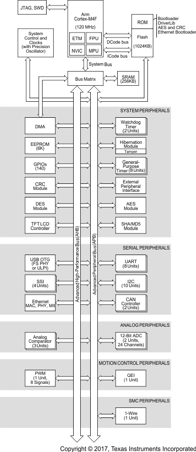
1.4 功能框图

Figure 1-1 给出了功能框图。

MSP432E411Y msp432e411y-high-level-block-diagram.gifFigure 1-1 MSP432E411Y 功能方框图

2 Revision History

DATEREVISIONNOTES
2017 年 10 月 * 初始发行版

3 Device Characteristics

Table 3-1 lists the characteristics of the MSP432E411Y MCU.

Table 3-1 Device Characteristics

FeatureDescription
Performance
Core Arm Cortex-M4F processor core
Performance 120-MHz operation, 150-DMIPS performance
Flash 1024KB of flash memory
System SRAM 256KB of single-cycle system SRAM
EEPROM 6KB of EEPROM
Internal ROM Internal ROM loaded with SimpleLink SDK software
External Peripheral Interface (EPI) 8-, 16-, or 32-bit dedicated interface for peripherals and memory
Security
Cyclical Redundancy Check (CRC) 16- or 32-bit hash function that supports four CRC forms
Advanced Encryption Standard (AES) Hardware accelerated data encryption and decryption based on 128-, 192-, and 256-bit keys
Data Encryption Standard (DES) Block cipher implementation with 168-bit effective key length
Hardware Accelerated Hash (SHA/MD5) Advanced hash engine that supports SHA-1, SHA-2, or MD5 hash computation
Tamper Support for four tamper inputs and configurable tamper event response
Communication Interfaces
Universal Asynchronous Receiver/Transmitter (UART) Eight UARTs
Quad Synchronous Serial Interface (QSSI) Four SSI modules with bi-, quad-, and advanced-SSI support
Inter-Integrated Circuit (I2C) Ten I2C modules with four transmission speeds including high-speed mode
Controller Area Network (CAN) Two CAN 2.0 A/B controllers
Ethernet MAC 10/100 Ethernet MAC with Media Independent Interface (MII) and Reduced MII (RMII)
Ethernet PHY PHY with IEEE 1588 PTP hardware support
Universal Serial Bus (USB) USB 2.0 OTG, Host, and Device with ULPI interface option and Link Power Management (LPM) support
1-Wire One 1-Wire module
System Integration
Micro Direct Memory Access (µDMA) Arm PrimeCell® 32-channel configurable µDMA controller
LCD Controller Configurable LCD controller with passive and active matrix LCD panel support
General-Purpose Timer (GPTM) Eight 16- or 32-bit GPTM blocks
Watchdog Timer (WDT) Two watchdog timers
Hibernation Module (HIB) Low-power battery-backed Hibernation module
General-Purpose Input/Output (GPIO) 18 physical GPIO blocks
Advanced Motion Control
Pulse Width Modulator (PWM) One PWM module, with four PWM generator blocks and a control block, for a total of 8 PWM outputs
Quadrature Encoder Interface (QEI) One QEI module
Analog Support
Analog-to-Digital Converter (ADC) Two 12-bit ADC modules, each with a maximum sample rate of 2 Msps
Analog Comparator Controller Three independent integrated analog comparators
Digital Comparator 16 digital comparators
System Management
JTAG and Serial Wire Debug (SWD) One JTAG module with integrated Arm SWD
Package Information
Package 212-ball NFBGA (ZAD)
Operating Range (Ambient) Extended temperature range (–40°C to 105°C)


Texas Instruments

© Copyright 1995-2025 Texas Instruments Incorporated. All rights reserved.
Submit documentation feedback | IMPORTANT NOTICE | Trademarks | Privacy policy | Cookie policy | Terms of use | Terms of sale