SSZTD13 October 2016 UCC28740
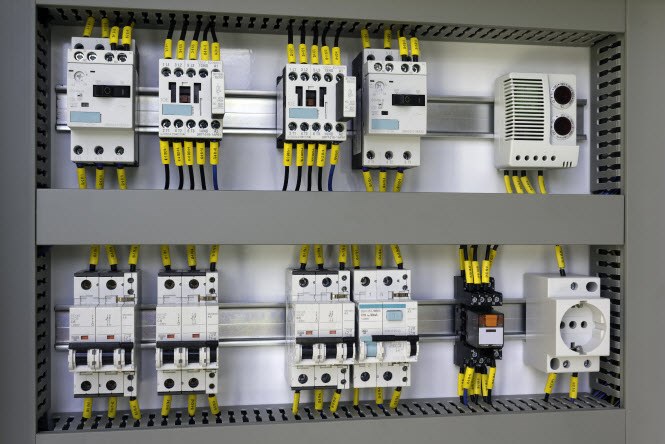
DIN rail power supplies in industrial equipment.
In this two-part series, I’ll explain the basic details of limited power source (LPS) requirements and how you can optimize the feedback loop with the UCC28740 primary-side regulated (PSR) flyback controller to reduce the overall components in high-power-density industrial DIN rail power supplies.
Increasingly, the responsibilities of a power-supply designer extend beyond merely meeting a product’s functional specifications. The latest-generation products need to be robust and safe over various operating conditions such as overcurrent, overvoltage, short circuit and limited power output.
To meet safety requirements for equipment powered using industrial power supplies, it is important to precisely limit current and power during all operating circumstances, which include normal conditions, load-transient conditions and severe output-fault conditions. In addition, the voltage should exceed certain limits to prevent electrical shocks for the end user. Limiting power, current and voltage also has a multitude of associated benefits, which include reduced wire gauges for output interconnections, reduced component stress for downstream converters, reduced system cost and increased system reliability.
Safety standards such as IEC - International Electrotechnical Commission IEC 60950-1 and the National Electrical Code (NEC) define these limits for voltage, current and power.
For instance, IEC 60950-1 covers LPS requirements of power supplies in Clause 2.5 of the standard, shown in Table 1. Table 2B of IEC 60950-1 Clause 2.5 elucidates the restrictions for power sources for current and apparent power for cases where you do not use external overcurrent protection such as inherently limited source.
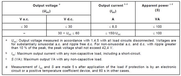
|
Figure 1 is a graphical representation of Table 1.
 Figure 1 Graphical view of UL60950
limited power circuits
Figure 1 Graphical view of UL60950
limited power circuitsSimilarly, the NEC also sets guidelines for maximum possible voltage, current and power to govern the installation of wiring and equipment in commercial buildings and residential areas.
In the next installment of this series, I’ll explain the protection implementation with minimal components.
Additional resources:
- Explore these industrial power-supply designs: