SSZTCO8 may 2015 INA199 , INA300
If you ask an engineer if they would like an efficient and reliable system, the answer will of course be yes. What that definition of efficiency and reliability is – and what it ultimately takes to get the system there – is not nearly as easy to answer.
In looking at reliability, a common place to start is to determine what level of protection will ensure that the system will be protected if any unintended operating conditions occur. Obviously, a fuse is an easy implementation to protect against a shorted condition for an overcurrent protection scheme. But then you have to worry about how to get that system back into the field after a fuse blows following a shorted condition. Operational downtime is expensive and, in many cases, unacceptable. The fuse only offers two pieces of information: whether or not the current is excessively high, and whether or not the system power bus has been opened.
A circuit that actively measures the system current can very precisely detect if an out-of-range condition exists and allow operating performance adjustments to enable safe operation up to the full power budget without sacrificing reliability.
The INA199 current-shunt monitor is a common building block for this function due to its small printed circuit board (PCB) footprint and accuracy, as well as its integrated, matched gain-setting resistors. The output is directed to a comparator with a fixed threshold corresponding to the current level the functional block is looking to detect, as shown in Figure 1.
 Figure 1 INA199 Current-shunt Monitor
in a Typical Application
Figure 1 INA199 Current-shunt Monitor
in a Typical ApplicationThe comparator output can directly control circuitry to open the power-supply bus, or allow a microcontroller to either throttle the system performance and continue operation within the allowable power budget or shut the system down altogether. For critical faults, this shutdown capability is extremely important to prevent the out-of-range condition from damaging system components.
The current-limit threshold for this circuit is set by the reference voltage applied to the noninverting input of the comparator. This voltage level directly corresponds to the current level measured by the INA199. Using a voltage divider, you can calculate the reference voltage with Equation 1:
The INA300 is a specialized current-sensing comparator that approaches this same function a little differently by integrating the current-sense amplifier and comparator into one device. Figure 2 shows this comparator in a typical application. The approach is the same as the previous example using the INA199, in that the INA300 has a threshold limit set using a single external resistor that corresponds to the current limit for the system.
 Figure 2 INA300 Current-sensing Comparator Block
Diagram
Figure 2 INA300 Current-sensing Comparator Block
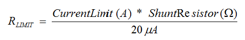
DiagramAn internal 20µA current source is present at the limit pin that creates a reference voltage for the comparator based on the value of the RLIMIT resistor connected to that pin. This voltage is set to equal the voltage developed across the shunt resistor at the current-limit level. Equation 2 calculates the RLIMIT resistor value:
I hope you are now familiar with how the INA199 and INA300 devices enable more effective detection and handling of overcurrent events. Stay tuned for the next part of my series, where I will discuss other ways system designers can take advantage of dedicated overcurrent detection. How do you define reliability and efficiency? Comment below to share your answer.
Additional Resources
- Learn more about TI’s current-sense portfolio.
- Watch this video about how the INA300 is optimizing overcurrent detection.
- Online training: Getting started with current-sense amplifiers.
- Check out these related TI Designs reference designs: