SSZTC79 september 2015 TMS320F28379D
In the first part of this blog series, Martin Staebler provided an overview of the various types of motor position encoders and their interfaces. In part 2, I’ll explain the interface to a bidirectional/ serial/ synchronous (BiSS) position encoder.
BiSS is an open-source protocol from iC-Haus. It defines a digital bidirectional serial interface for actuators and sensors like rotary or position encoders. (For more details, see www.biss-interface.com.) BiSS allows serial synchronous data communication in unidirectional or bidirectional modes known as BiSS-C continuous mode. The BiSS interface is hardware-compatible to the serial synchronous interface (SSI).
The BiSS protocol defines each subscriber/slave into data sections: sensor data, actuator data, register data and (if defined) multicycle data. Each data section can have various setups according to access and transmission performance, depending on the sensor application. To connect to the subscriber/slave a ”BiSS master” protocol is preformed, it sends and receives data to/from the position encoder. The BiSS master is software and is done on a host-processor such as a Sitara™ processor or FPGA.
The BiSS interface has two PHY options, one based on the TIA/EIA-422 standard and the other using LVDS TIA/EIA-644 standard. The typical interface is based on the TIA/EIA-422.
The BiSS has two different structure options: point to point and bus. In this post, I’ll focus on the point-to-point structure. For more information about bus structure hardware, see the design guide in the Interface to a 5V BiSS Position Encoder TI Designs reference design.
Today’s encoders typically use the point-to-point structure. When connecting a BiSS digital encoder with an RS422 or RS485 physical layer to a servo drive, I recommend shielded cables with twisted-pair wires. Encoder cables typically have six or eight wires for signal and power supply lines, as shown in Figure 1. Cable lengths of 100m and more are not unusual.
 Figure 1 BiSS-C Point-to-point
Structure
Figure 1 BiSS-C Point-to-point
StructureFigure 1 shows a typical BiSS configuration for position or rotary encoders. In a point-to-point configuration, only one device (with one or more sensors) is connected to the master.
The MA clock frequency is variable. The recommended MA clock frequency depends on the cable length, as outlined in Figure 1. I generated this figure using Table 1 in the application note “BiSS Interface AN15: BiSS C Master Operation Details.”
 Figure 2 Recommended BiSS MA Clock
Frequencies versus Cable Length
Figure 2 Recommended BiSS MA Clock
Frequencies versus Cable LengthWhen designing for the recommended frequencies of a BiSS interface, a 10MHz MA clock frequency would translate into an RS422/485 transceiver that can support 20MBaud. These are the minimum requirements. Tests performed using the Interface to a 5V BiSS Position Encoder TI Designs reference design showed that a faster transceiver will allow you to increase the cable length still using the maximum frequency of the protocol, as the transceiver is less noise sensitive to the cable distortions.
The power supply for a BiSS encoder would normally need to support the parameters shown in Table 1, although you should confirm this data with your encoder vendor’s data sheet.
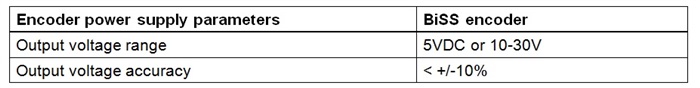 |
For the power supply, you will need to consider the voltage range that the encoder supports and how big the voltage drop of your cable is. One option is to use a programmable power supply that can change the voltage according to cable length. See the Power Supply with Programmable Output Voltage and Protection for Position Encoder Interfaces TI Designs reference design.
In the next session of this series of encoder interfaces, my colleagues and I will provide details on how to implement an industrial, EMC-compliant interface to an Endat2.2 position encoder.
Additional Resources
- Learn more about the Interface to a 5V BiSS Position Encoder TI Designs reference design for the hardware interface.
- For the BiSS master software example for Sitara devices, see the ARM MPU with Integrated BiSS C Master Interface TI Designs reference design.
- For more information on interfacing to a BiSS position encoder, check out the DesignDRIVE Position Manager technology and C2000 F28379 microcontrollers.
- Read other blogs about position encoders in this blog series.