SSZTC26 october 2015 LM25017 , LM25018 , LM25019 , LM5017 , LM5018 , LM5019 , LM5160 , LM5160A , LM5161 , LM5161-Q1 , TPS55010
Designing an isolated power-supply solution can be quite complicated; you need custom transformers, different types of feedback networks for proper circuit regulation and some type of compensation for stability. But for certain applications, one solution can provide the same required isolated bias without many of these design complexities: the Fly-Buck™ converter.
For those unfamiliar with the topology, the Fly-Buck converter creates isolated outputs using a synchronous buck regulator and coupled inductor windings (Figure 1). These designs offer several advantages over more traditional isolated power topologies. Since the isolated output closely tracks the primary-side output voltage, there is no need for an optocoupler or auxiliary winding; plus, you can use a smaller transformer since the primary and secondary turns ratios are better matched. This approach results in an isolated power design with both a lower cost and a smaller footprint. It also makes designing a stable and accurate isolated supply much simpler.
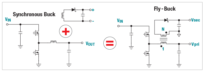 Figure 1 Fly-Buck Converter is Created
by Adding Coupled Windings to a Synchronous Buck Converter
Figure 1 Fly-Buck Converter is Created
by Adding Coupled Windings to a Synchronous Buck ConverterWhether you need a single isolated rail or a multi-rail power supply, WEBENCH Power Designer can now help you with your Fly-Buck designs. And just like any other power supply design, you have access to many of the useful features that WEBENCH Power Designer offers. Creating a WEBENCH Fly-Buck design is as simple as creating any other WEBENCH power supply design.
There are two ways to create a Fly-Buck design in WEBENCH Power Designer. The first method involves using the WEBENCH Designer panel. Using the panel, begin by clicking the “Start Design” button. Once the software has fully loaded, enter your Fly-Buck design requirements under the “Change Inputs” section (Figure 2).
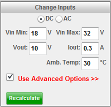 Figure 2 Enter the Power-supply
Requirements for Your Fly-Buck Design Using the Change Inputs Section
Figure 2 Enter the Power-supply
Requirements for Your Fly-Buck Design Using the Change Inputs SectionClick “Use Advanced Options” to open up the Advanced Options menu (Figure 3). Under Design Control, make sure that the “Show Alternate Topologies” checkbox is selected so that all possible Fly-Buck solutions will be listed. Once you’ve confirmed the selection of that checkbox, click the “Recalculate” button to proceed.
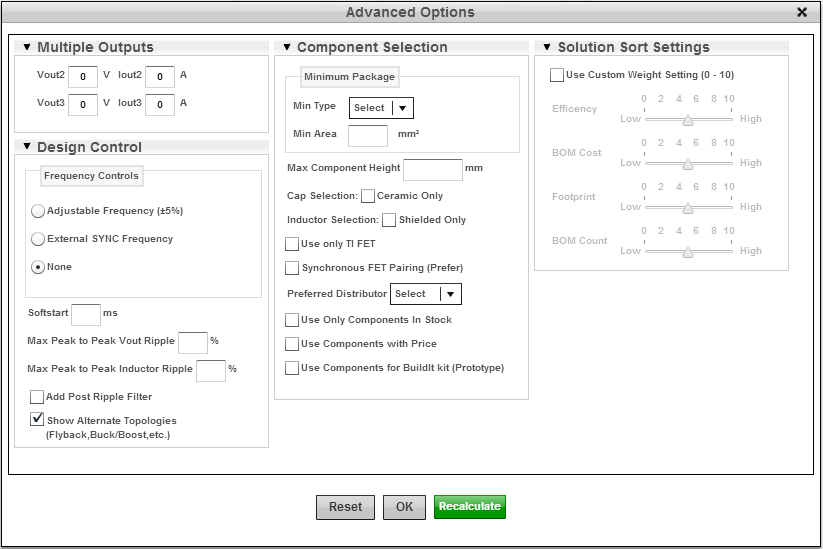 Figure 3 Use WEBENCH Advanced Options
to Show Alternate Topologies, Including Fly-Buck Designs
Figure 3 Use WEBENCH Advanced Options
to Show Alternate Topologies, Including Fly-Buck DesignsA list of viable solutions is provided in WEBENCH Visualizer, which allows you to easily sort and compare designs using different devices and topologies. Once you have found a Fly-Buck design that best suits your application, open it by clicking the “Open Design” button.
The second method requires you to know which device you plan to use for your Fly-Buck design. Let’s say, for example, that you plan to use the LM5160 for your Fly-Buck design. In the LM5160 product folder, you will find a WEBENCH Designer panel created specifically for this device (Figure 4).
Using the WEBENCH panel, enter the input requirements for your Fly-Buck design. Before opening the design, make sure the “Use Isolated Output?” checkbox is selected. This ensures that the design created in WEBENCH Power Designer uses the Fly-Buck topology as opposed to a regular buck topology.
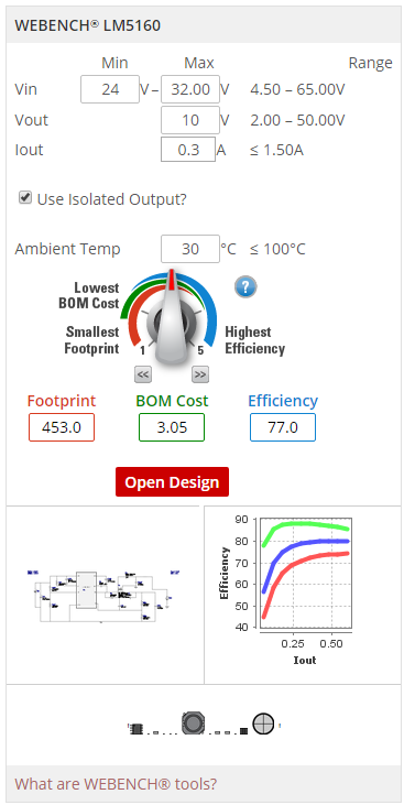 Figure 4 Using the WEBENCH Product
Folder Panel Allows You to Create a Fly-Buck Design Using a Specific Device Like
the LM5160
Figure 4 Using the WEBENCH Product
Folder Panel Allows You to Create a Fly-Buck Design Using a Specific Device Like
the LM5160Once the design is open, you can optimize the design with the optimization dial, view the design schematic, change the components in the bill of materials (BOM) window, print out a design report, or even share the design with a colleague (Figure 5).
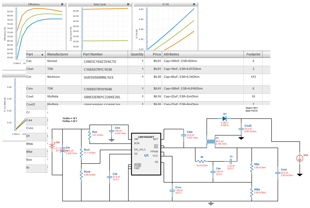 Figure 5 WEBENCH Tools Provide a List
of Power-dissipation Values, a Complete BOM and a Schematic for Your Fly-Buck
Design
Figure 5 WEBENCH Tools Provide a List
of Power-dissipation Values, a Complete BOM and a Schematic for Your Fly-Buck
DesignYou can even run SPICE simulations within WEBENCH Power Designer. Just click the “Sim” button, choose your simulation type (Steady State, Input Transient, Load Transient or Startup) and click “Start New Simulation”. When the simulation finishes, select the waveforms you wish to view in the Waveform Viewer (Figure 6). For further design customizations, WEBENCH Schematic Editor is also available.
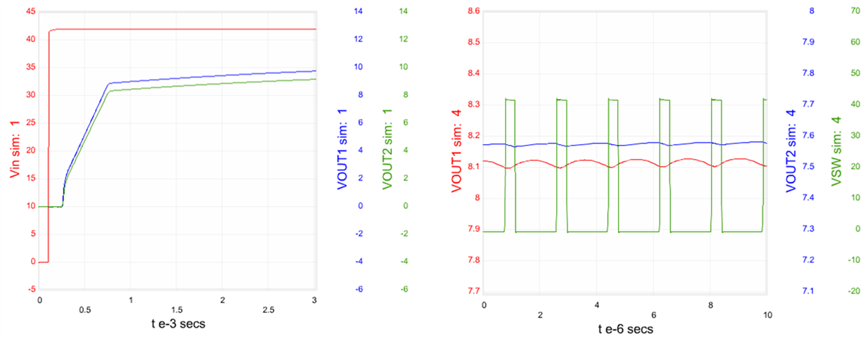 Figure 6 Startup and Steady-state
Waveforms Generated for a Fly-Buck Design in WEBENCH Power Designer
Figure 6 Startup and Steady-state
Waveforms Generated for a Fly-Buck Design in WEBENCH Power DesignerWEBENCH Power Designer currently supports the LM5017, LM5018, LM5019, LM25017, LM25018, LM25019, LM5160A and TPS55010 in the Fly-Buck configuration, with plans to support more devices in the future.
Whether you’ve worked with Fly-Buck converters before, or it’s your first time hearing about them, WEBENCH Power Designer makes designing these isolated power supplies quick and simple. In a matter of minutes, you’ll have a Fly-Buck solution in front of you, ready to be optimized, customized, and analyzed within the WEBENCH environment. Try it out for yourself, and if you have any questions, feel free to leave us a comment below. You’ll find that designing isolated power supplies has never been easier.
Additional Resources
- Check out this WEBENCH LM5160 Fly-Buck design, or start a Fly-Buck topology design now in WEBENCH Power Designer.
- Learn more about TI’s multi-output Fly-Buck topology.