SSZTBY0 november 2015 ADS8353 , OPA2365 , THS4531 , TLV3202 , TMS320F28069M , TPS54040A
The first part of this blog series provided an overview of the various types of motor-position encoders and their interfaces. Parts 2, 3 and 4 explained how to design an interface to absolute encoders with serial interfaces such as EnDat 2.2, bidirectional serial synchronous (BiSS) and HIPERFACE DSL. In this Part 5, I will introduce incremental sine/cosine (sin/cos) encoders with analog output and outline the design of an electromagnetic compatibility EMC-compliant interface.
Sin/cos rotary or linear encoders enable high-resolution position measurement. The high-resolution position is encoded into two 90° phase-shifted sinusoidal differential signals A+, A- and B+, B-, where the number of sinusoidal periods over one mechanical revolution equals the line count of the sin/cos encoder. A further differential analog output is the reference-marker signals R+ and R-, which allows for absolute-angle position detection. Figure 1 shows the output signals A, B and R, where A, B and R represent the differential signals of A+ minus A-, B+ minus B- and R+ minus R-, respectively.
 Figure 1 Output Voltage Signals a, B
and Marker R of Sin/cos Encoders with N Line Counts per Revolution
Figure 1 Output Voltage Signals a, B
and Marker R of Sin/cos Encoders with N Line Counts per RevolutionLet’s have a closer look at the typical electrical specification of sin/cos encoder’s output signals, as they are an important criterion for the specification of the analog components of the interface design.
The differential output signal amplitude is either 11µA-pp, or more commonly 1V-pp, with a typical 2.5V DC offset.
The frequency of the sin/cos encoder’s differential output signal, A and B, depends on the line count of the encoder as well as the mechanical speed, as outlined in Figure 2:
 Figure 2
 where N is the sin/cos encoder’s line count and v is the mechanical speed in revolutions per minute. Figure 3 lists typical examples for 1Vpp sin/cos encoders.
 Figure 3 Encoder Output Signals a, B
Examples
Figure 3 Encoder Output Signals a, B
ExamplesNow let’s have a look on how you decode the angle position from these output signals, as this is important for the system architecture of the interface design
A typical method to retrieve the sin/cos encoder’s angle uses separate hardware blocks for the incremental count (coarse angle) and the interpolated incremental phase (fine angle using the inverse tangent method), as outlined in Figure 4.
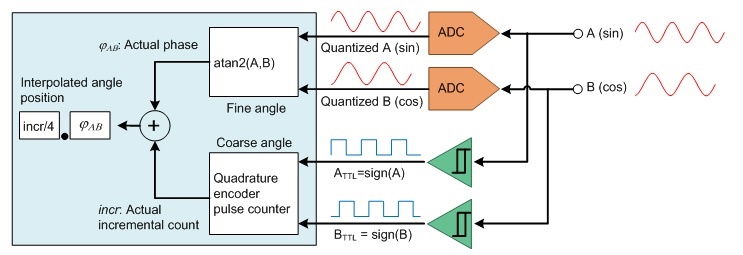 Figure 4
 Two comparators, one for sine and one for cosine, generate digital quadrature-encoded signals A and B, which drive a directional up- and down-counter, often referred to as a quadrature-encoded pulse counter. The analog bandwidth of the dual-sampling analog-to-digital converter (ADC) needs to be at least equal to the maximum sine/cosine frequency.
It is important that the sinusoidal signals, A and B, and the incremental count, incr, sample and latch simultaneously.
Practically, the digitized signals, ATTL and BTTL, have a phase shift compared to the analog signals. This phase shift is typically due to hysteresis and propagation delay of the comparators and nonideal sampling synchronization. This means that upon each transition to the next quadrant, the incremental counter may not be updated immediately because of phase lag. See the first quadrant in Figure 5.
 Figure 5 Phase Shift of aTTL
Versus Analog Signal a Due to Phase Lag
Figure 5 Phase Shift of aTTL
Versus Analog Signal a Due to Phase LagDue to the redundancy between the two least significant bits LSBs of incremental line count, which represent the four quadrants and analog phase, you can apply a correction method as outlined in Figure 6 as long as the phase shift (see the red and blue signals in Figure 5) remains less than ±90°.
Since only the phase information is used to identify the quadrant, there are only two exceptions to consider, where the phase doesn’t match to the incremental count. These exceptions occur during the transition from quadrant 4 to quadrant 1, or quadrant 1 to quadrant 4, depending on the rotation direction.
 Figure 6 Correction Method
Equation Figure 7 calculates the total high-resolution angle position, FTOTAL:
 Figure 7
 where N is the sin/cos encoder’s line count (number of signal periods per revolution), incr is the actual incremental count, and jA,B is the actual phase of the signals A and B calculated using the inverse-tangent method.
The ideal interpolated-angle resolution is a function of the sin/cos encoder’s line count, N, and the resolution of the dual ADC. Equation Figure 8 calculates the equivalent interpolated-angle resolution as:
 Figure 8
 For a sin/cos encoder with 1,024 line counts, the resolution is 22 bits when using a dual 12-bit dual ADC and 26 bits when using a 16-bit dual ADC. Such high resolution is often not required for position control but for precise speed control, especially at lower mechanical speeds.
A key analog component with an interface to sin/cos position encoders is the dual ADC. It might be external or embedded into the host processor.
Figure 9 shows the system block diagram of the TI Designs Interface to Sin/Cos Encoders with High-Resolution Position Interpolation reference design (TIDA-00176). The major building blocks are:
- An analog signal chain with
two options for flexibility:
- A 16-bit high-resolution fully differential path with SPI interface to a microcontroller (MCU).
- A analog path with a single-ended analog output for MCU-embedded ADCs.
- A high-speed comparator block.
- Power management.
- Example firmware on C2000™ Piccolo™ MCUs for digital signal processing, as indicated in the blue box in Figure 2.
 Figure 9 System Block Diagram of
TIDA-00176 with Piccolo F28069M MCU LaunchPad™ Development Kit
Figure 9 System Block Diagram of
TIDA-00176 with Piccolo F28069M MCU LaunchPad™ Development KitThe first building block is the dual-analog signal path with 120-Ω termination and EMC protection to connect the sin/cos encoder’s differential signals: A+, A-, B+, B-, R+ and R-.
The high-performance, fully differential signal path with high common-mode noise rejection leverages the THS4531 fully differential amplifier and the ADS8353 16-bit dual successive-approximation register (SAR) ADC with SPI interface to the host processor.
The single-ended analog signal path uses the OPA2365 which converts the differential analog inputs into single-ended analog signals A and B from 0 to 3.3V to drive an embedded dual sample and hold (S/H) ADC, like an embedded C2000 Piccolo MCU.
The second building block is the comparator block, which converts the analog signals A, B and R into digital signals with a 3.3V TTL I/O to interface to a quadrature-encoder pulse module like the enhanced quadrature encoder pulse (eQEP) module on the Piccolo MCU. The TLV3202 high-speed, low-propagation delay comparators are configured with hysteresis for better noise immunity.
The third building block is the wide-input-range 24V power supply, leveraging the TPS54040A high-efficiency DC/DC converter for an intermediate 6V rail and LDOs for point of load. The LDOs provide the necessary voltages for the signal chain as well as the 5.25V supply voltage for the sin/cos encoder.
The schematics and layout have been designed and tested for EMC immunity according to IEC618000-3, which specifies EMC immunity requirements for adjustable-speed electrical power-drive systems.
 Figure 10 IEC618000-3 EMC Immunity
Requirements and TIDA-00176 Test Results
Figure 10 IEC618000-3 EMC Immunity
Requirements and TIDA-00176 Test ResultsIf you’re ready to start designing, check out the TI Design Interface to Sin/Cos Encoders with High-Resolution Position Interpolation reference design, which outputs the measured angle from the sin/cos encoder with up to 28-bit resolution through a USB virtual communications port and includes example firmware for the Piccolo MCU. For an example with the Sitara AM437x processor including firmware check out the TI Design Interface to a Sin/Cos Encoder with Sitara™ AM437x Reference Design folder. A reference solution leveraging the C2000 DesignDRIVE Position Manager technology for on-chip interfacing to SIN/COS encoders is also included as part of the TI Design TIDM-SERVODRIVE.
In the next and final installment of this series, my colleagues and I will take a closer look at a universal multi-standard digital interface to absolute-position feedback encoders.
If you would like to see this series touch on specific topics related to position-encoder interface design, please post a comment below.
Additional Resources
- View these TI Designs reference designs:
- Order the C2000 DesignDRIVE development kit for industrial motor control.