SSZTBO2 january 2016
Selecting the inductance value for the output filter of a Class-D audio amplifier is always a critical design decision. With next-generation ultra-low-distortion Class-D amplifiers, selecting an inductor with poor electrical properties can severely limit the audio performance. My colleague Brian talked about how high-definition audio is changing the way we listen in his December blog post. In this post, I’ll discuss key considerations for selecting the right inductor to ensure your device is living up to its high-definition potential.
In higher-power Class-D amplifiers, (generally above 10W of output power), the passive output filter generally has both an inductor and a capacitor (LC) on each output terminal, and is thus referred to as an LC filter. The purpose of the LC filter is to convert the discontinuous pulse-width modulation (PWM) pulse-train output of a Class-D amplifier into a continuous smooth analog sinusoid. The LC filter extracts the audio signal from the PWM representation of the audio signal.
This filtering process is critical for a couple of reasons:
- Electromagnetic Interference (EMI) reduction. The PWM output of a Class-D amplifier is a high-amplitude voltage signal usually equal to the output stage or PVDD supply voltage. Filtering these pulses with an LC filter also filters the high-frequency content associated with the PWM pulses, reducing offending EMI emissions. With the LC filter placed as close as possible to the amplifier, long runs of speaker wire will not radiate EMI throughout the system.
- Reduced ripple current. For Class-D amplifiers with AD modulation schemes, but without an LC filter, there is a ripple current superimposed on the audio signal. With an LC filter, specifically as the cut-off frequency of the LC filter is reduced relative to the PWM switching frequency of the amplifier, the ripple current is also reduced such that only a small residual ripple will present after the LC filter. The reactance of the LC filter filters the rest of the ripple and ideally does not dissipate any power.
Let’s use the TPA3251D2 as an example. It is a 175W Class-D audio amplifier with total harmonic distortion and noise (THD +N) capable of approaching 0.001% in the mid power band. For the TPA3251D2, inductor linearity becomes critical to extract the highest level audio performance.
For this discussion, inductor linearity is defined as inductance vs. current.
An ideal inductor would maintain the specified inductance value no matter what current passes through it. However, real-world inductors always have decreasing inductance with increasing current. At some point, the current level will saturate the inductor and the inductance will fall off severely. This is often specified as Isat.
Keep in mind that the inductance change at the Isat current rating varies between manufacturers and even inductor types. Some manufacturers specify Isat at a 30% or higher change in inductance. If you expected to use this inductor all the way to the Isat rating for an LC Class-D filter, you would observe very poor audio performance.
Figure 1 shows data collected from 4 four different inductors that have good linearity specifications for high-performance Class-D audio amplifiers. I measured the inductance at 1A of current and again at 20A of current with a 600-KHz test signal, which is the nominal PWM switching frequency of the TPA3251D2 amplifier. The average change of inductance was calculated for 10 samples of each inductor.
 Figure 1 Average Change in Inductance
for 10 Samples of Four Inductor Types
Figure 1 Average Change in Inductance
for 10 Samples of Four Inductor TypesFrom the data above, the 10µH inductor from manufacturer A is more linear than the 10H inductor from manufacturer B. It is also important to note that the 7µH and 10µH inductors from manufacturer A are wound on the same core. Likewise, the 7µH and 10µH from manufacturer B are also wound on the same core.
Generally, the higher the inductance (the more turns of wire) for a given core material, size and geometry, the less linear the inductor.
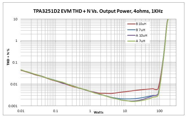
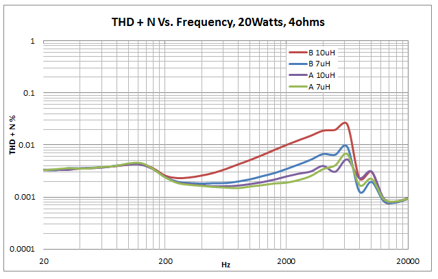
I then tested these inductors on the TPA3251D2 evaluation module (EVM) and the results were clear, as you can see in Figure 2 and Figure 3.
 Figure 2 TPA3251D2EVM Plot of
Output Power and THD+N for Measured Inductors
 Figure 3 TPA3251D2EVM Plot of THD+N
and Signal Frequency
Figure 3 TPA3251D2EVM Plot of THD+N
and Signal FrequencyFrom the data collected from the TPA3251D2EVM, the 10µH inductor from manufacturer A outperforms manufacturer B’s 10µH and 7µH inductors. If I were to select manufacturer B’s 10µH inductor, the THD performance of the amplifier would be limited to 0.0045% at 10W, compared to 0.0017% for the manufacturer A’s 10µH inductor.
Also notice that at 20W, the THD vs. frequency performance improves significantly. If you were designing an LC filter around an amplifier where higher THD performance is acceptable, or if the native THD of the amplifier was higher, the 10µH from manufacturer B may be a suitable candidate. In the end, the designer of the system must make a choice between inductor linearity, cost and size.
Other considerations such as switching losses or ohmic losses under high output power levels will determine which inductor is best for a given system. However, by selecting an inductor with greater linearity, you can improve the THD performance of a Class-D amplifier significantly, as demonstrated with the ultra-low THD of the TPA3251D2.
If you have worked with a Class-D amplifier before, log in and leave a comment below. I’m interested in learning more about which inductor you chose and the resulting performance.
Additional Resources
- Search TI’s entire high-power Class-D amplifiers portfolio.
- Read the TPA3251D2 data sheet.
- Check out the TPA3251D2D2 PurePath™ ultra-High Definition evaluation module.
- See other recent audio blogs.