SSZTBH6 march 2016 TPS62097
Industrial system designers typically standardize on one or two devices to provide a given function across their products. For example, they might use one or two power-supply integrated circuits (ICs) to operate from various power sources, such as 5V adapters or single-cell battery packs. Or they might use a general-purpose operational amp lifier to amplify or condition signals from a variety of sensors. Standardization allows for more design reuse, as well as greater volumes on the few common components that they do use. This reduces R&D effort and provides a greater pricing advantage due to the economies of scale.
One challenge in standardization is, of course, providing a flexible enough device that can fulfill multiple roles. For a power supply, this can mean having both a low quiescent current (IQ) for use in portable applications but also a low-noise output when output ripple is more critical. This is a challenge, since these are conflicting goals for a power supply. With the shrinking size of all electronics, size is important as well. But can such a small device have enough features, which require dedicated IC pins and space, to fit into different applications?
With iDCS-Control (which stands for industrial direct control with seamless [iDCS] transition into power-save mode), the answer is yes. As implemented in the TPS62097, iDCS-Control includes features that meet a variety of industrial applications, while keeping everything you love about DCS-Control. These features include a selectable forced pulse-width modulation (PWM) mode, selectable switching frequency, 1% output-voltage accuracy, and sequencing and tracking with soft start, all contained in a single device. Let’s briefly look at each feature.
Selectable Forced PWM Mode
A MODE pin supports either low-noise applications or high-efficiency portable applications. You can change this MODE pin during operation to make your portable application be low noise (forced PWM mode) at critical times, like when you read a sensor or transmit on a radio, and high efficiency (power-save mode) for other times. Figure 1 shows the efficiency difference, while Figure 2 shows the output-ripple difference. The 40µA IQ enables high light-load efficiency for many portable applications.
 and Forced PWM Mode (Right)") Figure 1 TPS62097 Efficiency with
Power-save Mode (Left) and Forced PWM Mode (Right)
Figure 1 TPS62097 Efficiency with
Power-save Mode (Left) and Forced PWM Mode (Right) and Forced PWM Mode (Right)") Figure 2 TPS62097 Output Ripple with
Power-save Mode (Left) and Forced PWM Mode (Right)
Figure 2 TPS62097 Output Ripple with
Power-save Mode (Left) and Forced PWM Mode (Right)Selectable Switching Frequency
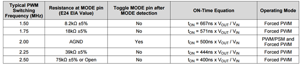
Certain sensors or radios may have critical frequency bands that you must avoid. The TPS62097 supports five different switching frequencies, which enables you to tune the switching frequency to different points for different applications. Frequencies between 1.5MHz and 2.5MHz are supported; this includes three frequencies above the AM radio band. Table 1 shows the choices you have for your application.
|
1% Output-voltage Accuracy
A high-accuracy output voltage is required in more and more applications to provide the load with just the right voltage. The DC accuracy of the power supply is a key contributor to overall power-supply accuracy. Figure 3 shows 1% accuracy over temperature and load, which is a key step toward meeting the stringent 3% overall accuracy demanded in some systems.
 Figure 3 Output-voltage Accuracy over Temperature and Load
Sequencing and Tracking with Soft Start
A SS/TR pin provides a variety of functions, especially for powering field-programmable gate arrays (FPGAs). Connecting a capacitor to the pin controls the output-voltage startup time, which usually must be within a certain range when powering FPGAs. Or you can drive the pin with another system voltage in order to track it – this is sometimes required for FPGAs as well. Figure 4 shows two of these tracking possibilities. Of course, the TPS62097 also has the standard enable (EN) and power good (PG) pins for simple sequencing requirements.
 Figure 4 Output-voltage Tracking Possibilities
How will you use the feature-rich iDCS-Control to improve your industrial system?