SSZTBH1 March 2016 ISO5851 , ISO5852S
In my earlier blog posts on isolation, I’ve mentioned one of the key applications of isolation: protection against electrical shock.
In high-voltage applications, a failure of the isolation barrier can result in a potential operator safety hazard or cause damage to sensitive control circuitry, leading to system malfunction. Therefore, it is important to understand what may cause the isolator to fail, both under normal and fault conditions. You need to know the nature of the failure in each case to know if you need to put additional measures in place to prevent an electrical hazard.
So what causes an isolator to fail?
The first failure mode (failure mode 1) is when a high voltage exceeding the isolator’s rated specifications occurs across the isolation barrier, resulting in insulation breakdown. This high voltage could be in the form of a sinusoidal voltage lasting a few seconds or minutes, a surge impulse due to direct and indirect lightning strikes, or a continuous overvoltage lasting months or years. Figure 1 shows this failure mode.
Failure mode 1 occurs in all isolators and couplers, magnetic, capacitive and optical, irrespective of type and construction. It is easy to avoid in the final system: just choose an isolator whose rated specifications exceed the voltages expected in the end equipment under all conditions. End-equipment standards (such as International Electrotechnical Commission (IEC) 61800-5-1 for adjustable speed motor drives) make this choice simple by establishing clear guidelines to ensure electrical safety. TI’s reinforced isolators provide one of the highest isolation ratings in the industry, and hence crucial margin against failure mode 1 in several applications.
 Figure 1 Failure Mode 1 Is a High
Voltage across the Isolation Barrier
Figure 1 Failure Mode 1 Is a High
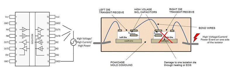
Voltage across the Isolation BarrierThe second failure mode, failure mode 2, occurs when a high-power event, defined as a combination of a high voltage and high-current events, occurs on one of the sides of the isolator. The excessive heat and mechanical stress caused by such an event can destroy the associated silicon die. The insulation in TI’s reinforced isolators is made of a series combination of two high-voltage capacitors placed on two different silicon dies. Even if one die is damaged due to electrical overstress, the other die remains intact, providing basic isolation. This characteristic is called “fail open” behavior. Failure mode 2 is shown in Figure 2.
 Figure 2 Failure Mode 2 Is High Voltage
and High Current Close to an Isolation Barrier
Figure 2 Failure Mode 2 Is High Voltage
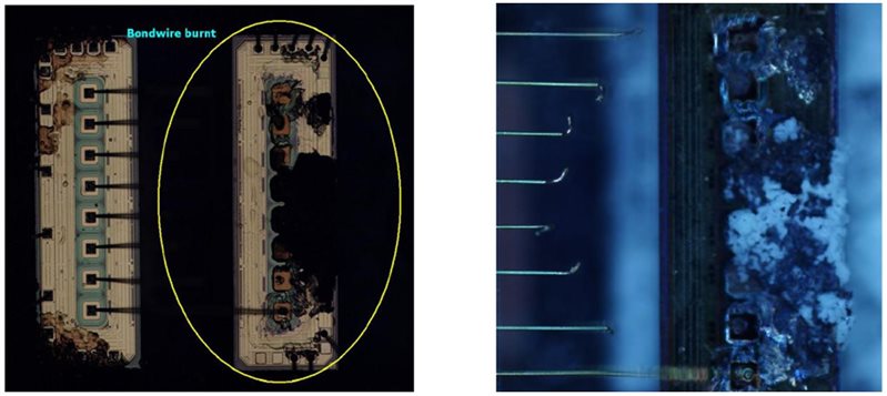
and High Current Close to an Isolation BarrierFigure 3 shows photographs of a decapsulated TI-reinforced isolator showing one half of the isolation intact, even after being subject to surge voltage on one of the two sides. Many competition isolation solutions do not use two separate isolation barriers in series, and hence can be “fail short” in similar situations, compromising electrical safety.
 Figure 3 TI-reinforced Isolators
Survive Failure Mode 2
Figure 3 TI-reinforced Isolators
Survive Failure Mode 2In our white paper, “Understanding failure modes in isolators,” Neeraj Bharadwaj, Kannan Soundarapandian and I discuss this topic in detail. In this white paper, we also show several experimental results that demonstrate the fail open behavior of TI-reinforced isolators.
How is isolation making your system safer? Log in to post a comment below.
Additional Resources
- Read the data sheets for TI’s ISO5851 and ISO5852S isolated gate drivers, AMC1305 isolated delta-sigma modulators and ISO78xx digital isolators. Download the whitepaper “Isolation in AC Motor Drives: Understanding the IEC 61800-5-1 Safety Standard”.
- See TI’s entire isolation portfolio.