SSZTBD2 may 2016 DAC161S997 , LM5165 , LM5165-Q1 , LM5166
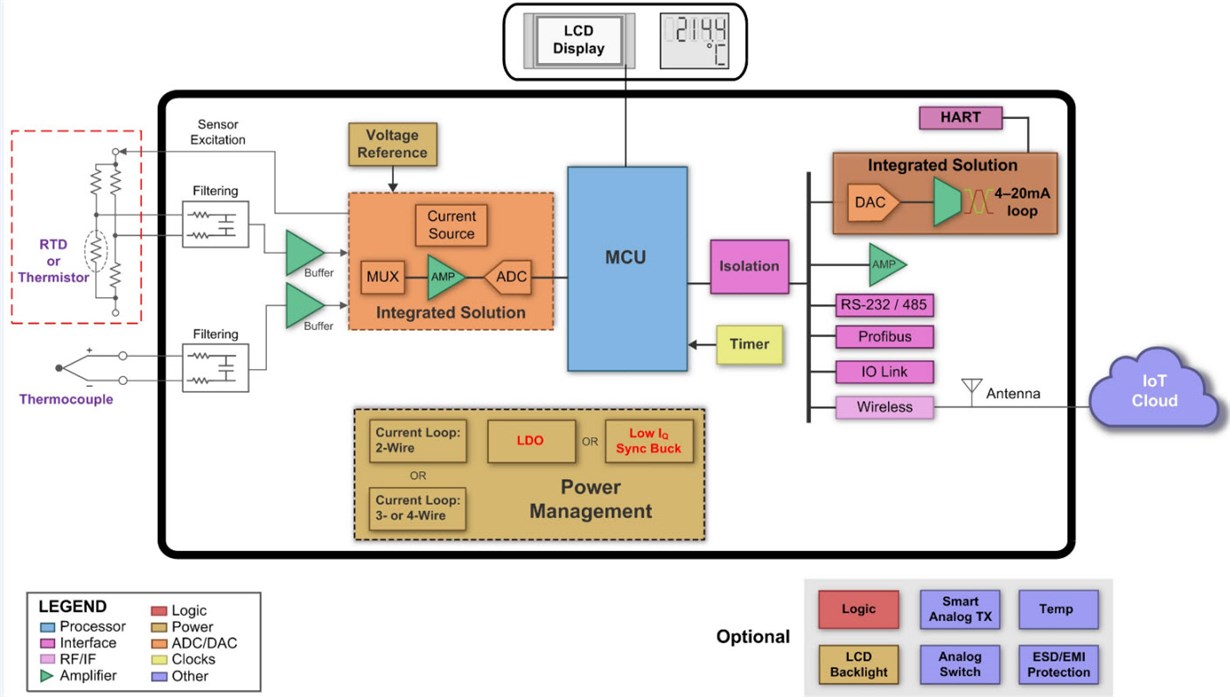
Smart sensor transmitters are widely used in factory automation, process instrumentation and control equipment to measure temperature, pressure, flow, level and many other process variables. Figure 1 is a block diagram of a field transmitter that measures temperature as the primary variable using a resistance temperature detector (RTD), thermistor or thermocouple.
 Figure 1 Temperature Transmitter Block
Diagram for Process Control Applications
Figure 1 Temperature Transmitter Block
Diagram for Process Control ApplicationsThe signal chain includes the sensor analog front end, microcontroller (MCU), and high-precision analog-to digital and digital-to-analog converters.
Powering Smart Sensors from the 4-20mA Loop
While a basic sensor transmitter circuit’s MCU and data converters are usually optimized for low operating current, the added functionality in high-performance smart sensor applications leads to increased current demand. For example, current consumption is greater when the circuit includes features such as isolation, calibration and diagnostics, a liquid crystal display (LCD) interface, or wireless connectivity options such as Bluetooth® low energy or wireless HART®.
Such intelligent sensor systems may not be able to meet typical underscale current thresholds or the 4mA zero-scale level of the 4-20mA current loop. For example, the default loop currents that demarcate low- and high-error currents for TI’s DAC161S997 are 3.375mA and 21.75mA, respectively. The NAMUR NE43 specification has similar current thresholds. Fortunately, a high-efficiency synchronous buck converter provides higher output current than a low-dropout regulator (LDO) to power sensor electronics, while harvesting less than 3.375mA from the loop.
Wide vIN, Low IQ Synchronous Buck Converter
For powering sensors, the LM5165 synchronous buck solution from TI has high-efficiency and ultralow quiescent current (IQ = 10.5uA). Operating from a 20:1 wide input-voltage (VIN) range and capable of sustaining repetitive 65V surges, its output voltage is immune to large and noisy voltage swings at the input. Such transient immunity performance is critical in sensor applications that require high reliability.
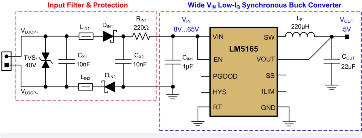
Figure 2 shows the converter schematic configured for an output of 5V at 25mA. Adding an input filter with reverse polarity and transient/surge voltage protection helps achieve electromagnetic compatibility (EMC).
 Figure 2 Pulse-frequency Modulation (PFM) Synchronous Buck Converter Schematic, Including an EMC Filter and Protection Circuit
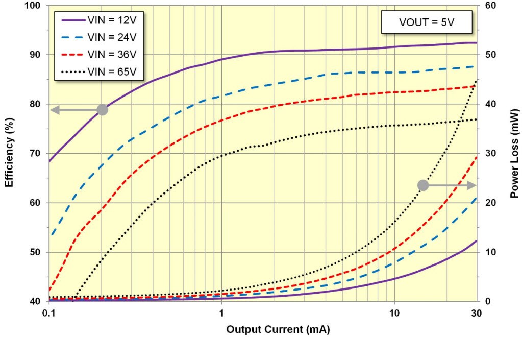
Various features incorporated in the LM5165 for smart sensor applications include a simple control architecture for optimal solution size, 100% duty cycle capability for low dropout, an open-drain power-good circuit for power-rail sequencing and fault reporting, internally fixed or externally adjustable soft start (SS), and precision enable with customizable hysteresis for programmable-line undervoltage lockout (UVLO). Also, an adjustable cycle-by-cycle current limit optimizes inductor selection and sizing. Figure 3 shows the converter efficiency and power dissipation for a load current from 0.1mA to 30mA.
 Figure 3 Typical Efficiency of the LM5165 Buck Converter (Output Rated for 5V at 25mA)
Value Proposition of a Wide vIN, Low IQ Buck Converter
The benefit of a wide VIN buck converter such as the LM5165 lies in its cohesive feature set, which addresses a specific set of power solution needs:
- Synchronous buck design with high efficiency over a wide load current range.
- Enhanced reliability with an operating junction temperature rated to 150°C.
- Wide VIN range with enough margin to survive input-voltage transient disturbances, allowing the use of a higher voltage (and smaller footprint) transient suppressor diode (TVS).
- Small solution size for space-constrained sensor housings.
- Reduced input capacitance to meet requirements for intrinsically safe (IS) application environments.
- Active slew-rate control of the switch-mode voltage reduces high-frequency conducted and radiated EMI signatures.
To exploit the full potential of modern loop-powered sensor transmitters and retain the simple two-wire architecture, the LM5165 low IQ synchronous buck converter delivers adequate load current while meeting current loop, solution size, reliability and EMC requirements.
Additional Resources
- Read more about two-wire, 4-20mA sensor transmitters in TI’s Precision Hub blog.
- Order the PFM and constant on-time (COT) evaluation modules for the LM5165 synchronous buck converter.
- Use the LM5165 quick-start design tool to expedite a design and examine the converter’s efficiency plotted over log and linear scales of output current.