SSZTB93 may 2016 TPS53317A , TPS54620
As I travel and meet with customers across many market sectors, I have come to realize that many hardware designers become power-supply engineers by necessity. Hardware designers are responsible for designing voltage regulators that remain electrically and thermally stable under operating and expected worst-case conditions; meet the required power specifications of processors, application-specific integrated circuits (ASICs), double-data-rate (DDR) memory, hybrid cube memory and field-programmable gate arrays (FPGAs); and generate low electromagnetic interference (EMI). The job of a voltage regulator is to keep its output voltage constant (regulated) though line (input voltage), load (output current) and environmental variations.
Step-down (buck) voltage regulators are the most commonly used switching-regulator topology. Several voltage regulators are typically found in boards used in wired/wireless communication, enterprise server/storage, industrial and personal electronics. Today’s switching-voltage regulators have a plethora of control and protection features to ensure power-supply protection, reliability and output-voltage tolerance.
Let’s review some of their features.
- Power good and enable: Power good is an output flag that indicates if the voltage regulator’s output voltage is within a pre-determined/programmed output-voltage window. Once the voltage reaches that window, it is on its way to the final programmed value, which is a good sign. Power good can be an active high or low signal.
Enable is an on/off input signal that can also be active high or low. Enable turns the voltage regulator on or off. If the voltage regulator has soft start, it will start in soft start, assuming that its input voltage is above the undervoltage lockout (UVL) threshold. If there’s a delay from the enable signal to soft start, the regulator will soft start after that time delay.
Power good and enable are often used for sequential power sequencing of multiple power supplies on the same board as shown in Fig.1
 Figure 1 Power Good and Enable for
Power Sequencing
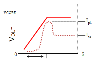
- Soft start: Soft start turns
the voltage regulator on slowly to the programmed duty cycle and output
voltage so that output current ramps slowly, reducing inrush current as
shown in Fig.2. Inrush current could cause output-voltage overshoot and a
system glitch or damaged power stage. Inrush current happens when a board’s
bulk capacitors are discharged and must then charge all at once when input
power is present. Soft start also avoids current limits that could shut the
DC/DC converter down (latch off). Soft start is usually adjustable or
selectable through an external capacitor or a pin-strap setting (connecting
the soft-start pin to existing voltage rails on the board).
 Figure 2 The Soft Start of
a Voltage Regulator and Corresponding Soft-start Current
(Output)
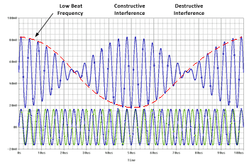
 - Frequency synchronization:
Frequency synchronization refers to the voltage regulator’s internal
oscillator (clock) synchronizing to an external clock and switching
frequency to match that of the external clock’s switching frequencyy. This
is especially beneficial when more than one voltage regulator is present on
the same board. Their fundamental switching frequencies can generate
harmonics, which can then can generate beat frequencies that can make their
way to the output in the form of noise if the audio rejection and filtering
are poor as shown in Fig.3. Frequency synchronization is great for radio
frequency (RF) or data-acquistion applications like base stations and
medical imaging.
 Figure 3 Frequency
Synchronization
 - Pre-bias operation. A pre-bias startup condition occurs as a result of the presence of an external voltage at the output of a voltage regulator before that output becomes active. This is typically due to leakage currents in ASICs and processors that charge the output even after power down. When the regulator is enabled, it soft starts the high-side (switching) FET and its duty cycle ramps from zero to the required duty cycle for voltage regulation. If during soft start the synchronous FET is on when the high-side FET is off, the synchronous FET sinks current from the output by discharging the output capacitors through the inductor, causing the core voltage to drop and potentially causing the power supply to shut down.
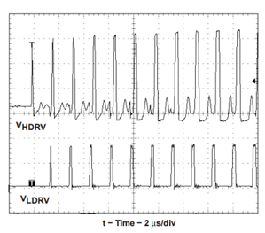
A voltage regulator with pre-biased capability will disable full synchronous rectification (holding the low side off) during initial soft start, start the first low-side FET on pulses with a narrow on-time, and then incrementally increase that on time cycle by cycle until it coincides with the time dictated by (1-D), where D is the buck regulator duty cycle. Essentially, pulse-width modulation (PWM) pulses start when the error-amplifier soft-start input voltage rises above the programmed feedback voltage value (Figure 4). This ensures that the output capacitors do not discharge during soft start. Pre-bias relies on the input voltage being always higher than the output voltage. The output-inductor current sources current to charge the output capacitors only until the output voltage reaches the regulation value.
 Figure 4 MOSFET Drivers at Beginning of
Soft Start under Pre-biased vOUT
Figure 4 MOSFET Drivers at Beginning of
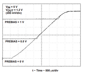
Soft Start under Pre-biased vOUTFigure 5 shows startup waveforms of a 1.2V VOUT voltage under different pre-bias scenarios. The first trace is when the output voltage starts with zero pre-bias. The pre-bias levels of the second and third traces are 0.5V and 1.0V, respectively. When a pre-biased voltage is present at the output, the regulator will begin soft start from that voltage level onwards. TI buck regulators like the TPS53317A have pre-biased startup capability.
 Figure 5 Voltage Regulator Startup
Waveforms under Pre-biased VOUT
Figure 5 Voltage Regulator Startup
Waveforms under Pre-biased VOUTUnderstanding voltage-regulator features can demystify the idea that power supplies are an opaque black box. In future posts, I will look at other voltage-regulator features and how they relate to power-supply design and performance.