SSZTB89 june 2016 TPS25924 , TPS25942A , TPS25942L , TPS25944A , TPS25944L
During our journey down the Yellow Brick Road, we have discussed eFuse options for both overvoltage protection (OVP) and overcurrent protection (OCP). In this final installment, I will discuss how an eFuse recovers from thermal shutdown. In other words, how does it recover and resume normal operation? Let’s start by taking a look at the available fault-response options, as shown in Figure 1.
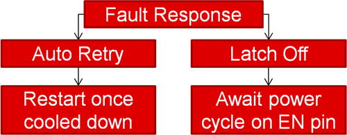 Figure 1 eFuse Fault-response Options
(Auto Retry and Latch off)
Figure 1 eFuse Fault-response Options
(Auto Retry and Latch off)The Benefits of Auto Retry
First, let’s analyze the more common option: auto retry. In part 2 we used the TPS25944A to understand circuit breaking eFuses. For a quick refresher: when this device sees an overcurrent event, it will break the circuit, causing IOUT = 0A, and report the fault by asserting the FLT pin. Once it has reported the fault, it will begin to auto retry (it just so happens that the “A” in TPS25944A stands for auto retry). An auto-retry eFuse will then automatically restart and attempt to restore normal operation (continuing to “retry” until the fault is removed). You can see this power cycling in Figure 2.
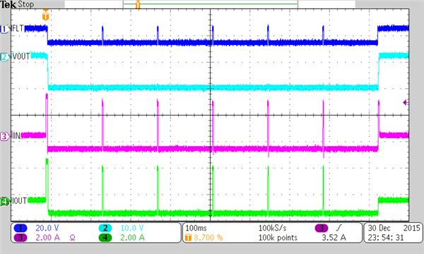 Figure 2 TPS25944A Circuit Breaking and
Auto Retrying
Figure 2 TPS25944A Circuit Breaking and
Auto RetryingAs long as the fault condition is present, the eFuse will continue to turn on, break the circuit, and turn off again. That is why you see a spike of activity (the eFuse turns on) followed by a pause (the eFuse breaks the circuit and turns off). This pattern changes for a current-limiting auto-retry device, like the TPS25942A, as shown in Figure 3.
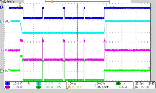 Figure 3 TPS25942A Current Limiting and
Auto Retrying
Figure 3 TPS25942A Current Limiting and
Auto RetryingAlthough similar to Figure 2, there is now a longer “spike” of activity. As I discussed in part 2, the TPS25942A eFuse will current limit until it reaches thermal shutdown, and then turn back on once cooled down. Both the TPS25944A and TPS25942A will continue to power cycle and automatically retry until the fault is removed. The difference is that the current limiter (TPS25942A) is thermal cycling, while the circuit breaker (TPS25944A) is not. It is worth noting that this thermal cycling is within normal operating parameters and will not damage the eFuse.
The Benefits of Latching off
In contrast to auto-retry functionality, an eFuse that latches off will turn off and stay off until told to turn back on. This means that if IIN > ILIM, the TPS25944L (“L” for latch off) will immediately break the circuit (IOUT = 0A) and turn off. To an outside observer, Figure 4 may look like the TPS25944L walked through a field of poppies and fell asleep, falling for the Wicked Witch of the West’s clever trap.
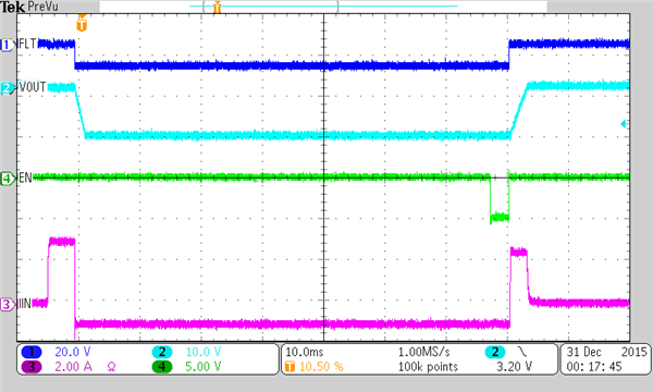 Figure 4 TPS25944L Circuit-breaker
Latch-off Functionality
Figure 4 TPS25944L Circuit-breaker
Latch-off FunctionalityOnce the EN pin toggles (see the green line in Figure 4), however, it wakes right back up. The device never fell asleep or was in any way broken – it was patiently awaiting a power cycle on the EN pin to tell it to turn back on. Looking at the current limited latch-off TPS25942L, you see a very similar response, except that this device current limits until thermal shutdown before latching off (Figure 5).
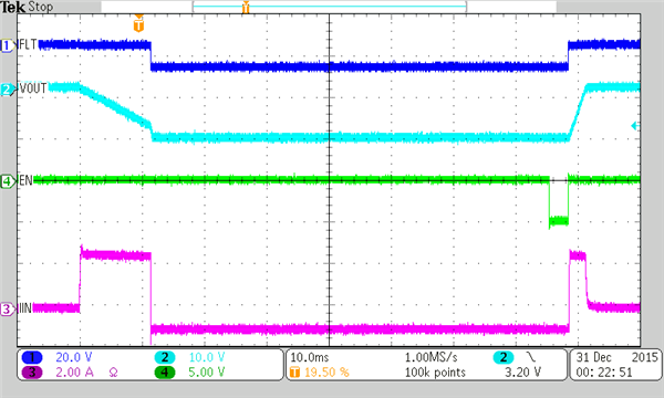 Figure 5 TPS25942L Current-limiter
Latch-off Functionality
Figure 5 TPS25942L Current-limiter
Latch-off FunctionalityRegardless of whether the latch-off eFuse has circuit breaking, current limiting, clamping or cutoff, when it encounters a fault it will turn off and stay off. Going back to our example from part 2, when I discussed smoke or fire prevention, this functionality proves very useful for immediately disconnecting a problematic or faulty component from the system. After the eFuse asserts the FLT pin, the system can decide how to respond. While a system with circuit-breaking and latch-off functionality may be a safer system (as it quickly removes the faulty component), it can also reduce uptime. For every set of system requirements, TI has an eFuse to maximize both uptime and system reliability.
Selecting Your Next eFuse
While there are no part-number indicators for OVP or OCP options, all eFuses represent their fault response via the last character before the package designator. Some product families use “0” and “1” to designate auto retry and latch off (Figure 6), while others (like the TPS2594x family) use a trailing “A” or “L,” as shown in Figure 7.
 Figure 6 TPS25924 Device Comparison Table
 Figure 7 TPS25942/44 Device Comparison Table
I hope this series has demystified the myriad of protection features available with Texas Instruments eFuses. While on the Yellow Brick Road of circuit design, if you have further questions, please feel free to leave a comment, post in the TI E2E™ Power Management Forum. As Glinda the Good Witch of the North once said, you’ve always had the power to select the right eFuse; you just had to learn it for yourself!
Additional Resources
- Check out these TI Designs reference designs:
- Read my colleague Kathrina Macalanda’s blog post, “Get out of the dark: Upgrade your fuse!”
- Review the first and second installments of this blog post series.