SSZTB87 june 2016 LM25066 , LM25066A , LM25066I , LM25066IA , LM5064 , LM5066 , LM5066I
In my last blog, I walked through how to simplify a robust hot swap design using online design calculator tools. In this post, we’ll look at using the PI-Commander GUI as another means to help design a digital hot swap controller.
Located on the front end of many systems, hot swap controllers control the flow of power to the load and protect against fault conditions. Their location at the input makes them good candidates for monitoring the voltage, current and power going into a board. As a result, many hot swap controllers have integrated amplifiers and analog-to-digital converters (ADCs) and can report these measurements to an external microcontroller via I2C/PMBus.
Getting started with digital power management using hot swap controllers can be a simple process. Design tools such as the PI-Commander GUI can significantly reduce development time by serving as a proven test bed to evaluate or troubleshoot the performance of a system.
For example, are you trying to read a current measurement but the result is far off? If you are already using proper sense-resistor layout techniques, then the issue could lie in software implementation.
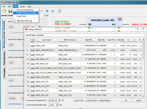
The PI-Commander GUI offers detailed information about the b, m and R coefficients used in calculating current measurements in accordance with the PMBus protocol. Simply select View > PMBus Coefficient Editor (Figure 1). Then enter the current-limit threshold and current-sense resistor values in order to see the corresponding b, m and R coefficients.
 Figure 1 PMBus Coefficient Editor
within the PI-Commander GUI
Figure 1 PMBus Coefficient Editor
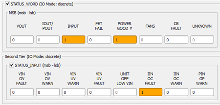
within the PI-Commander GUIOr maybe your hot swap circuit is shutting down unexpectedly. If so, check out the PMBus Register Page in order to find out why. You may notice a fault register such as STATUS_WORD showing an INPUT fault and POWER GOOD is low. If you dig deeper into the STATUS_INPUT register, you can see in Figure 2 that the IIN OC FAULT bit was set, indicating that an input overcurrent event caused the hot swap controller to shut off.
 Figure 2 STATUS_WORD and STATUS_INPUT
Registers within the PMBus Register Page within the PI-Commander GUI
Figure 2 STATUS_WORD and STATUS_INPUT
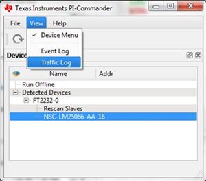
Registers within the PMBus Register Page within the PI-Commander GUILastly, if PI-Commander GUI is working well in your system but your custom microcontroller/software implementation is still having an issue, perhaps you could use help interpreting the raw I2C communication. The PI-Commander GUI features a Traffic Log (see Figure 3) that observes and records the raw hexadecimal values communicated via I2C by the host (PI-Commander GUI) and values received by the slave (hot swap controller).
 Figure 3 Select View > Traffic
Log to Open the Traffic Log Window
 Figure 4 Observe and Record Traffic
Log Information When Selecting Update Status or Update Telemetry on the
PMBus Register Page
Figure 4 Observe and Record Traffic
Log Information When Selecting Update Status or Update Telemetry on the
PMBus Register PageAs hot swap controllers become an integral part of digital power management, a need exists for comprehensive digital design tools. The PI-Commander GUI saves digital power designers time by offering the features necessary to quickly evaluate and troubleshoot a digital hot swap circuit design.
Learn how TI’s vast collection of hot swap design calculator tools can save you time.