SSZTB40 July 2016
Welcome to the fourth post in this series about the controller area network (CAN). In my last post, I focused on how a typical CAN output driver topology works; in this post, I’ll build off of the typical CAN driver topology and show why termination is so critical for proper communication with CAN.
The International Organization for Standardization (ISO) 11898 CAN standard specifies that the physical wires of a CAN network be single-twisted-pair cable with 120Ω of characteristic impedance. Furthermore, the standard states that both ends of the bus must be terminated with resistors equal to the cable’s characteristic impedance.
As I showed in my previous post, a typical CAN driver has an “open-drain” output structure, meaning that the dominant edge is actively driven and the recessive edge is not. Therefore, properly terminating the bus is very important because it ensures that the recessive edge decays properly, and in time for the next bit’s sample point.
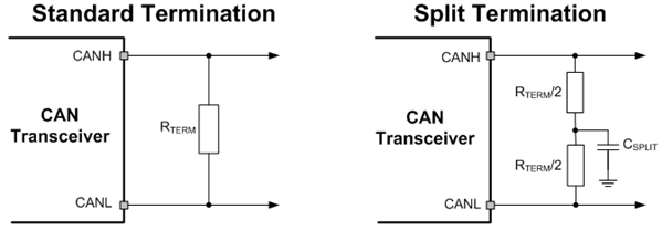
Terminations can come in many different flavors, but Figure 1 shows the two most common bus-termination techniques: standard termination and split termination.
 Figure 1 Common CAN Termination
Techniques
Figure 1 Common CAN Termination
TechniquesStandard Termination
The standard termination consists of a single-resistor termination between CANH and CANL, shown on the left in Figure 1. This technique entails placing a single resistor that matches the cable’s differential-mode characteristic impedance, which is usually 120Ω, between the CANH and CANL bus lines for each termination.
Split Termination
The split termination technique, shown on the right in Figure 1, uses two resistors that are equal to one half the cable’s characteristic impedance (typically 60Ω each), with a capacitor placed between the common-mode point and ground (typically between 1-100nF).
Although the split termination technique uses more components, it offers the added benefit of creating a low-pass filter for the common-mode noise on the network, and thus can aid in improving electromagnetic emissions. The resistors and capacitor (RC) create an RC low-pass filter with a corner frequency shown in Equation Figure 1:
 Figure 2 (1)
Typical concerns I have heard with this termination technique include, “Will this filter my CAN bus signals?” and “Do I need to place the corner frequency above my data rate?” The simple answer to both questions is no. Since the capacitor does not place a direct current (DC) load on the differential bus signal – it only filters the alternating current (AC) signal and the common-mode signal – and the differential signal is what determines the bus state, you do not need to set the corner frequency of the filter above the data rate.
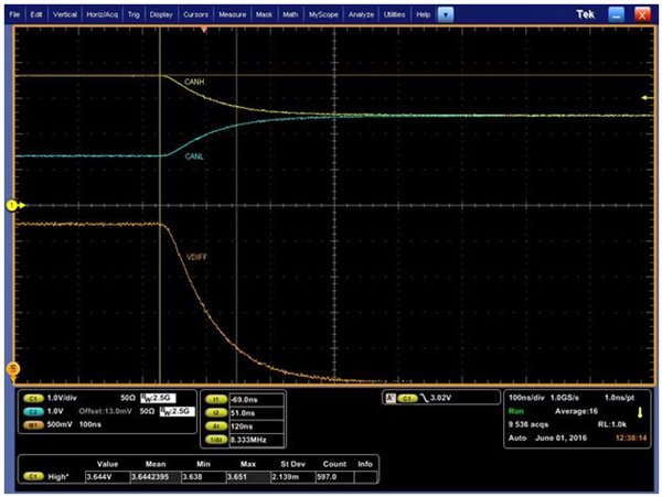
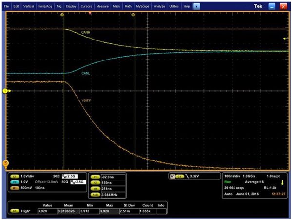
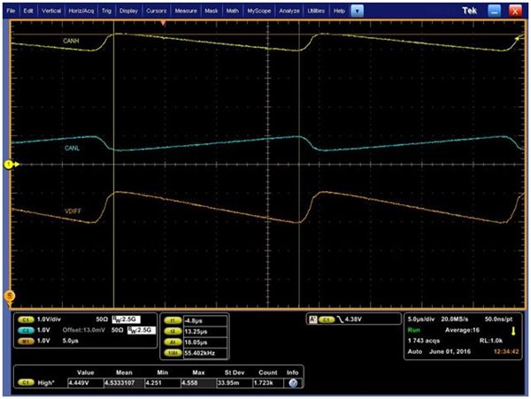
A sometimes overlooked issue that results in an improperly terminated bus is when a node or nodes that have integrated termination are uninstalled from a network. This results in a half-terminated or possibly unterminated CAN bus. Figure 3, Figure 4 and Figure 5 show CAN bus signals with three different termination scenarios:
- Figure 3 is an example CAN transceiver with both ends properly terminated with standard terminations.
- Figure 4 shows the same CAN transceiver with only one of two standard terminations populated.
- Figure 5 shows the same CAN transceiver with both standard terminations missing.
 Figure 3 CAN Bus Signals with Two Standard Terminations
 Figure 4 CAN Bus Signals with Only One Standard Termination (and One Missing)
 Figure 5 CAN Bus Signals with No Termination (Both Missing)
As you can see when comparing Figure 4 to Figure 3, when you lose one of the two terminations, the recessive edge takes over twice as long to decay (120ns vs. 251ns). This delay will increase with larger and more capacitively loaded networks. For the scenario shown in Figure 4, with no termination resistors the bus will not decay back to the recessive state even after 18.0µs! For cases where the RC delay is too slow, the next bit’s sampling point would occur before the bus returns to a differential voltage of less than 500mV and would therefore cause a bit error.
This RC delay will vary from network to network and will depend on the differential load that transceivers place on the network in parallel, as well as all of the capacitance due to cabling, protection and filtering components. Therefore, it is important to place terminations either externally to all of the network nodes, or on nodes that will never be uninstalled, as this will avoid major signal-integrity issues that can occur from an improperly terminated bus.
The last thing that you need to consider when selecting your termination resistors is how to size them. Depending on the faults that can occur in the system, the resistors need to be rated to handle possible fault currents. The usual worst-case fault would be to have a supply wire shorted to CANH, where CANL would cause large currents when driving a dominant signal. For a 12V supply and a 120Ω impedance, the resistor could have as much as 100mA of current though it. It is therefore important to use resistors with power ratings high enough to handle possible bus-fault conditions.
As you can see, while CAN termination is a fairly straightforward topic, it can lead to communication issues if not done properly. In the next installment of this series, I will discuss how split termination can help improve electromagnetic emissions, and show CAN bus signals and conducted emissions plots with and without split termination.
What challenges do you face when communicating with CAN transceivers? Log in to leave a comment or visit the E2E™ Community Industrial Interface forum.
Additional Resources
- Check out our entire CAN transceiver portfolio.
- Download the white paper, “Simplify CAN bus implementations with chokeless transceivers.”
- Jump-start your design with the TI Designs IEC 61000 ESD, EFT and Surge Protected CAN Reference Design (TIDA-00629).