SSZTAY9 august 2016 LMG3410R070 , UCD3138A , UCD7138
Wide-bandgap power devices such as gallium nitride (GaN) and silicon carbide (SiC) field effect transistors (FETs) have become commercially available in recent years. Compared with high-voltage (≥600V) silicon FETs, GaN and SiC FETs generally have lower on-resistances (Rds(on)), lower output capacitances (Coss) and fewer/no reverse recovery charges (Qrr). Due to their lower switching losses, you can greatly increase the efficiency of a hard-switching converter with wide-bandgap power devices.
Applying GaN FETs to resonant converters improves efficiency by reducing magnetic losses. Let’s take an inductor-inductor-capacitor series resonant converter (LLC-SRC), shown in Figure 1, as an example. An LLC-SRC uses the energy stored in the resonant inductor (Lr) to discharge MOSFET output capacitors in the input switch network. If the output capacitor voltage discharges to zero before the MOSFET gate signal goes high, you can achieve zero turn-on loss.
 Figure 1 An Llc Src
Figure 2 shows key waveforms of an LLC-SRC. During the MOSFET’s switching transient, iLr equals the maximum current flow through Lm, expressed as Equation 1:
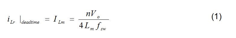
The current ILm – assumed constant during dead time – discharges the Coss of one MOSFET and charges the Coss of another MOSFET. Assuming the Coss of the two MOSFETs of the half bridge are the same and that you can ignore the interwinding capacitance of the transformer, Equation 2 expresses the maximum inductance with which you can achieve zero turn-on losses:

 Figure 2 LLC-SRC Switching
Waveforms
Figure 2 LLC-SRC Switching
WaveformsNow let’s presume you’re choosing between a GaN FET and silicon FET on the same 400VIN to 12VOUT conversion specification using an LLC-SRC. TI’s LMG3410 GaN device has a 70mΩ on-resistance and a 95pF output capacitance (energy related). One 70mΩ silicon FET I found has a 140pF output capacitance. If your selected turns ratio is n = 16 and the target maximum switching frequency of the LLC-SRC is 750kHz, Lm,max will be 134µH for TI’s LMG3410 and 91µH for the silicon FET with the 140pF output capacitor. As the input switches, the air gap of the LLC-SRC transformer with the silicon FET will be wider than the transformer with the LMG3410 if you apply the same core. Because of the wider air gap, there will be more eddy current losses on the transformer wires.
Figure 3 shows the thermal performance of the same LLC-SRC with different transformer air gaps under the same test conditions. As you can see, the wire losses on the transformer with the wider air gap are much higher than the one with the narrower air gap. Therefore, using GaN devices with lower Coss can help reduce magnetic losses in resonant converters.
 (a); and Lm = 70µH (Wider Air Gap) (b)") Figure 3 LLC-SRC Transformer Thermal
Performance at 400VIN, 12V/42A Output with Lm = 100µH
(Narrower Air Gap) (a); and Lm = 70µH (Wider Air Gap) (b)
Figure 3 LLC-SRC Transformer Thermal
Performance at 400VIN, 12V/42A Output with Lm = 100µH
(Narrower Air Gap) (a); and Lm = 70µH (Wider Air Gap) (b)While in this post I discussed a benefit of using GaN devices on resonant converters – lower output capacitance enabling fewer transformer losses – TI GaN devices such as the LMG3410 offer not only low Rds(on) and Coss but also incorporate several protections such as overcurrent and overtemperature protection. With all of these protections, converter reliability improves greatly.
In my next post, I will discuss power-supply reliability with TI GaN devices in more detail.
Additional Resources
- More detail information of TI GaN devices can be found in the following articles:
- If you are interested in using TI GaN devices in your power supply designs, take a look at the following reference Design