SSZTAX9 september 2016 LP2985-N , MSP430F5528 , MSP430FR2633 , TPD4E004
In the second installment of this blog series, I explored safety and security, the second of several trends in building automation wireless sensor networks. As a recap, the key trends driving the addition of more sensors in a building automation system include:
- Energy efficiency.
- Safety and security.
- User comfort.
In the third installment, I’ll go over user comfort which, when added to buildings, creates a comfortable atmosphere as well as a seamless and modern user experience when interacting with various sensor nodes.
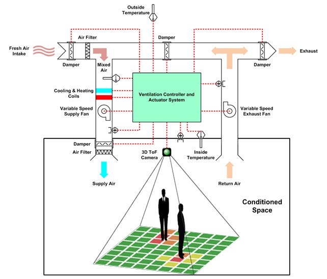
The first post in this series discussed stand-alone environmental sensors that can enable more intelligent heating, ventilation and air conditioning (HVAC) control by monitoring the temperature and humidity in multiple rooms or zones. I also discussed increasing HVAC system efficiency through demand-controlled ventilation (DCV) based on the number of people occupying a room rather than the room’s maximum occupant number. Figure 1 shows an example DCV system using 3D time-of-flight (ToF). The second post briefly touched on gas and particle detection, which can help HVAC systems bring fresh air into a room based on its air quality. As you can see, sensor-node trends may intersect with one another. Intelligent control for a comfortable environment can lead to energy-efficient buildings and create a clean, well-maintained atmosphere. Relating back to this infographic, optimizing the work environment can contribute to a 3% increase in employee productivity.
 Figure 1 3D ToF Camera-based DCV
System
Figure 1 3D ToF Camera-based DCV
SystemI’d like to explore another aspect of user comfort, which is the user experience when interacting with sensor nodes.
Smartphones and other mobile devices have enabled a multi-layer graphical user interface (GUI) on any wirelessly connected sensor node, either through Bluetooth®, Wi-Fi® or a cloud-connected sensor gateway. This multilayered GUI has created sensor nodes that do not require physical buttons or user interaction, but it also creates questions: how do end users know that the device accepted their remote input and executed the necessary commands.
Let’s use a modern automobile as an example. If I use a key fob to lock my car, the car will respond by executing the commands, flashing the headlights and sounding an audible tone. This gives me two ways of verifying that my message was received and that the car is locked.
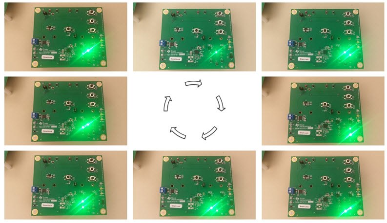
You can apply this concept for new building or home automation applications such as electronic locks, smoke detectors or even gateways. You can include additional LED functionality in the form of a quick flash, an always-on indicator or a pattern based on the end equipment’s need. Figure 2 is an example of pattern based LED functionality. You could also add multiple colors (such as red, green, blue (RGB) LEDs) to denote system status including system OK, system connected, system in alarm or battery low.
 Figure 2 Pattern-based LED
Functionality
Figure 2 Pattern-based LED
FunctionalityIn these instances, users will see or hear status notifications through LEDs or audio outputs while keeping the main user interface remote. But in many cases, you may still want to create a local user interface.
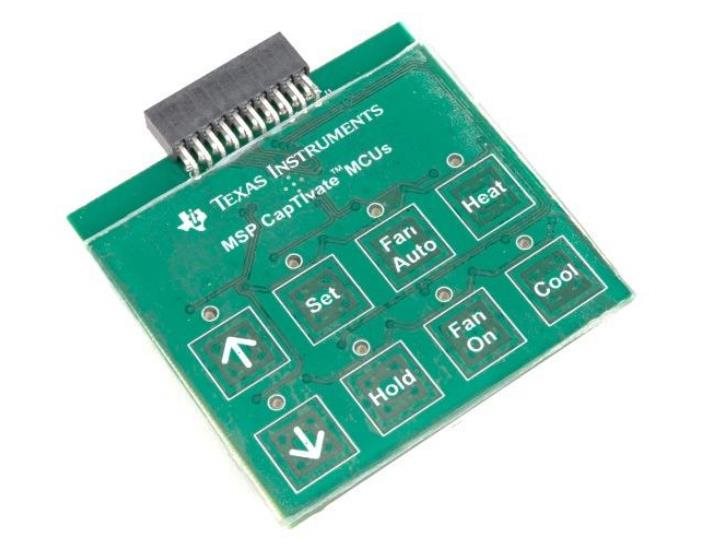
Traditional mechanical buttons are a great, inexpensive option that provides a familiar look and feel. But other button options exist that help mitigate existing concerns with mechanical buttons, including stuck buttons, buttons falling between air gaps or even customizability. Technologies including capacitive touch (as shown in Figure 3) and touch-on-metal enable a clean surface without button gaps, a customizable button layout and an environmentally robust design. You can include additional design flexibility with haptic feedback, applying custom waveforms with a piezo or haptic driver based on the system or the button’s function type. Thus, you can create a fully customizable user-interface solution from button layout, to button-press feedback, to button-depress feedback.
 Figure 3 An Eight-button Custom MSP430™
MCU with CapTIvate™ Touch Technology Layout
Figure 3 An Eight-button Custom MSP430™
MCU with CapTIvate™ Touch Technology LayoutFor a jump-start on connected sensing, be sure to check out these building automation reference designs and the additional resources below.
Additional Resources
- Check out these TI Designs reference designs for wireless sensor networks:
- Capacitive touch keypad: Capacitive Touch Thermostat UI with MSP MCUs Featuring CapTIvate Technology Reference Design (TIDM-CAPTIVATE-THERMOSTAT-UI).
- Read Pradhyum Ramkumar’s blog post, “Captivate touch in industrial HMI.”
- Read Rodney Miranda’s blog post, “Solving the problems of mechanical buttons and capacitive touch sensors.”
- Read Luke LaPointe’s blog post, “Inductive sensing: rethink the button.”