SSZTAQ7 october 2016 LM3710 , LM8365
In the first installment of this series, I defined voltage detectors and supervisors/reset ICs and explained different output types, along with some basic devices. As designs become more complex, more advanced devices may be required to successfully monitor a voltage. In this installment, I’ll highlight various features found in voltage detectors and supervisors/reset ICs to help designers select the right one.
Programmable Output Delay
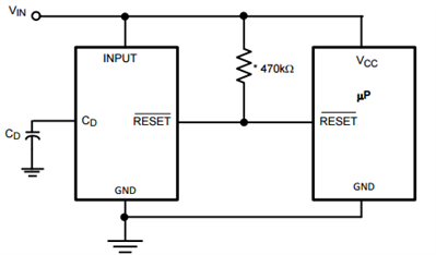
 Figure 1 LM8365 Typical Application Circuit with Programmable Output Delay
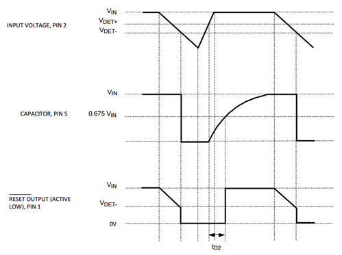
When the input voltage drops below the reset threshold, the reset pins drops low. When the input voltage rises above the threshold, there is a delay before the reset pin comes back up. By increasing the capacitor (CD), the delay increases. See the timing diagram for the LM8365 in Figure 2.
 Figure 2 Timing Diagram for the LM8365
Manual Reset
Power-fail Input
Watchdog Timer
Low-line Output
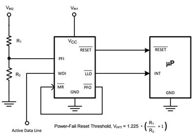
 Figure 3 LM3710 Application Circuit
In addition to the standard reset, the LM3710 has a manual reset, power-fail input, watchdog timer and low-line output, making it a very flexible device for many applications. The application circuit shown in Figure 3 above uses R1 and R2 as a voltage divider connected to VIN2 to set the power-fail reset threshold in order to monitor a second power supply. If the second power supply drops below the power-fail reset threshold, the PFI pin will be low, so the PFO pin will also drop low. Since this pin is connected to the MR pin, a reset will trigger.
A reset will also occur if no activity is detected within the watchdog window on the WDI pin. The WDI pin can connect to the microprocessor to detect if it is still operating correctly by having the microprocessor send an intermittent pulse. The low-line output (LLO) pin will drop low if the supply voltage at VCC drops to within about 2% of the reset voltage threshold. The LLO pin, for example, can connect to a microprocessor for detection. When the LLO pin goes active, a signal sent to the microprocessor can cause some other action to occur such as sending a signal to another device or a flashing LED or some other alert to the user.
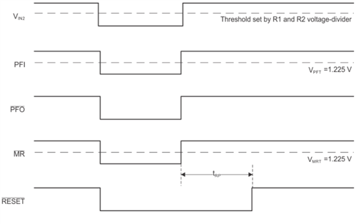
 Figure 4 Example Timing Diagram for Power-fail and Manual Resets of the LM3710
The timing diagram in Figure 4 shows an example of monitoring a second voltage input (VIN2). When the VIN2 connected to the PFI pin goes low, the PFO pin drops low, causing the MR pin to drop low, which then triggers a reset. There are many ways to use the power-fail and manual reset features, so it is up to you to decide what you need for your application.
After reading Part 1 and Part 2 of this blog series, you should be aware of the subtle difference between voltage detectors and voltage supervisors/reset ICs along with the various features that are available. There are countless applications that require detecting a supply voltage beyond a set voltage threshold and it is up to the designer to determine what happens next. When your battery is low, for example, do you want your system to flash a light or turn on a speaker or turn off some other device in your circuit? Do you want the user to be able to press a button to trigger this same condition or some other condition? Do you want to be able to monitor multiple voltages at different thresholds? When choosing a voltage detector or supervisor/reset IC, first determine what you are trying to do and what features you need then you can narrow down the devices by the specific specs, package, cost, etc. To see all of the voltage detectors and supervisors/reset ICs offered by Texas Instruments, see the voltage detector and supervisor/reset IC selection guide website.