SSZTAP2 november 2016 ADS8320 , BQ25570 , CC2650 , LM5166
Have you ever wondered where manufacturers get those nice rounded-off numbers for maintenance timelines? Who decided that every 5,000 miles was the best time to change your vehicle’s oil? The truth is, in some cases, it isn’t. With technology advancing by leaps and bounds, there has been a major focus on implementing a method of proactive maintenance based on perceived future need, not a specific time period or mileage. We call this technology predictive maintenance.
Sensors integrated strategically on or in a device collect data that when analyzed can detect a potential part failure. These sensors range from infrared temperature sensors to piezoelectric vibration sensors. The key is selecting the right sensor and placement for the job, which is as easy as determining what you want to detect. The placement can get a little tricky, however (especially in the example I’ll discuss in this post), but every system is different. Where there is a will, there is a way.
Preventive or periodic maintenance, a term that most of us are probably used to hearing, does not take into account the accelerated system degradation or unique environmental conditions that a predictive system can. Periodic maintenance can actually lead to premature product failures due to warning signs that may go undetected for long periods of time because it is not yet due for PM., This can also lead to wasted costs based on unnecessary over-maintenance. Over time, these costs can build up into quite a tidy sum – much more than the cost of additional sensors and a few lines of logic. That being said, the benefits of predictive maintenance are already emerging from the crystal ball.
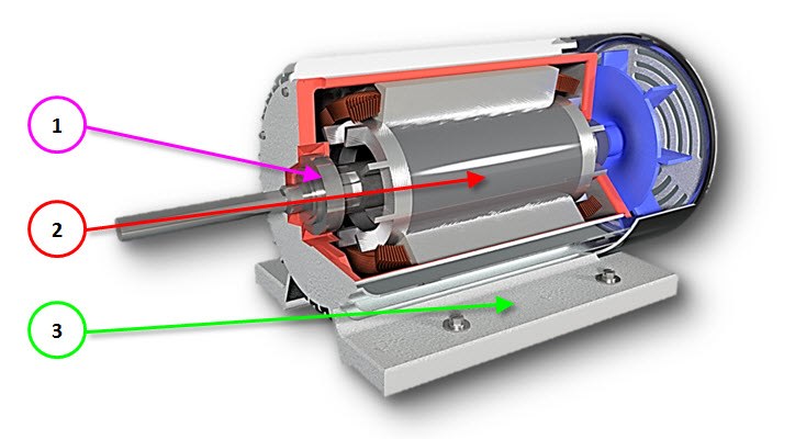
Let’s look at an example of a predictive maintenance implementation in a typical real-world application. Figure 1 shows an electric rotary motor used in a variety of industrial applications. By integrating temperature sensors along the rotor bearings and stator, along with a vibration sensor on the motor chassis, you can detect several issues that can occur with these motors. As you recall, I said placement can be quite tricky. In this particular instance, placement of sensors on the stator is easy, but rotor bearing placement can be difficult due to tight encapsulation and lack of access. Nevertheless, it can be done, and used to detect issues such as:
-
Bearings:
- Damaged bearings.
- Oil whirl and whip in bearings.
-
Stator:
- Shorted rotor bars.
- Loose stator laminations.
-
Motor chassis:
- Loose stator support.
- Mechanical looseness.
 Figure 1 Cross-section of a Rotary
Motor
Figure 1 Cross-section of a Rotary
MotorWith this simple example, it’s easy to justify the need for these types of technological implementations in everyday electromechanical (or perhaps strictly mechanical) systems. This type of maintenance technology is designed to alleviate unplanned downtime and ensure optimal operating conditions. Check out the Wireless Motor Monitor Reference Design, which captures the essence of predictive maintenance systems targeting motor applications. These types of systems are emerging quickly, especially in industries such as heating, ventilation and air conditioning/refrigeration, where the market previously held a strong mechanical focus with respect to innovation.