SSZTAO1 november 2016 UCC28C42
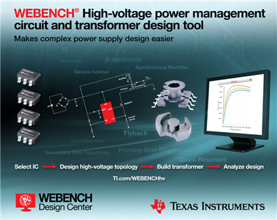
High voltage power supplies are ubiquitous whether you are designing an AC/DC adapter or your high voltage on-board power supply for industrial applications. You find them commonly to step down your high voltage input voltage to a lower intermediate voltage before you power your point-of-load (POL) converters. The design of these front-end power supplies pose unique challenges from the requirements that they have. This post is intended to give you a basic understanding of high-voltage power-supply design, and how design tools can make it simple to design for these applications. There are three main things that you need while designing for your AC/DC or high-voltage DC/DC application.
1. Understand Your System Requirements.
If your power supply requires tight regulation of the output, you need to consider secondary-side regulated controllers that tightly regulate the voltage on the secondary, versus primary-side controller regulators where the output could vary with changes in the transformer or secondary diode parameters. Certain applications require that your transformer provide a certain class of isolation for safer, robust end equipment.
TI’s WEBENCH® High-Voltage Power Designer is an easy to use tool to design your AC/DC or HV-DC/DC applications. You simply enter your voltage and current requirements and find solutions that work for your application. With the optimizer dial, you can optimize your design for cost, footprint and efficiency based on your system needs. To get started, visit the WEBENCH panel on ti.com. Figure 1 shows a view of the power solutions generated by WEBENCH Power Designer.
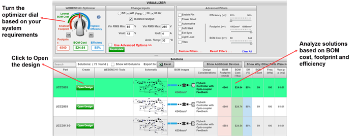 Figure 1 WEBENCH Power Designer with High Voltage Solutions
Figure 2 shows an AC/DC flyback using primary-side regulation that provides a low-cost, low-footprint solution, as well as loose regulation of the output on the secondary. Figure 3 shows an AC/DC flyback in secondary-side regulation using optocoupler feedback, which is more expensive but provides tighter regulation on the secondary.
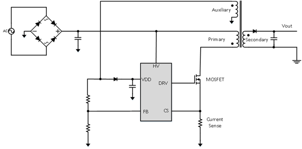 Figure 2 AC/DC Flyback with Primary-side Regulation
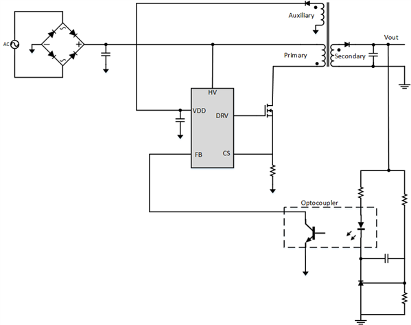 Figure 3 AC/DC Flyback with Secondary-side Regulation Using Optocoupler Feedback
2. Select the Right Topology/control Scheme.
WEBENCH Power Designer saves you time and effort by creating the complete design for the topology using the necessary equations depending on the device and its operating mode. The tool also lets you evaluate efficiency and also other parameters such as output ripple, the RMS currents, losses etc. at various operating points within the design range.
3. Design Your Transformer.
Transformers typically have a core (which is the magnetic element); the bobbin (or coil former), which is the plastic housing for the core (see Figure 4); and the wire that gets wound on the core-bobbin structure.
 Figure 4 Core, Coil Former and Assembled Transformer
Assembled pre-built transformers are readily available from manufacturers with a fixed turns ratio (Ns/Np) and primary inductance (the magnetizing inductance of the transformer that causes energy to build up). Depending on the operating frequency and output power levels, the requirements for the primary inductance and the turns ratio vary widely, and a pre-assembled off-the-shelf transformer might not be available. In such cases, selecting a transformer core and bobbin and winding the transformer will be necessary. This requires an in-depth knowledge of transformer magnetics.
WEBENCH design tools now give you the ability to design the transformer by selecting the core and bobbin that meet the requirements and also provides the winding structure details as well. You can click on the transformer symbol in the schematic to view and download the transformer details and also to change the transformer core/bobbin combination. Figure 5 shows a view of the transformer design window giving you the various core/bobbin combinations for a specific design requirement. You can also compare different transformers in terms of height, losses (core/copper losses), footprint and cost. If you have a preference for a specific core type or material, use the transformer listing to pick the one that is appropriate for your needs.
The transformer construction diagram gives you instructions on how to wind the transformer. This along with the transformer construction details table gives you information on the number of layers, strands, the AWG of the wire and more. You can also download the transformer design report as shown in Figure 6 to get this information. This will simplify your effort to build the transformer whether you are prototyping it yourself or having it wound by a transformer winding company.
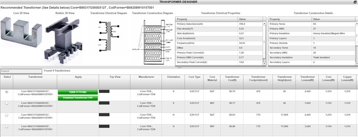 Figure 5 Transformer Design Capability in WEBENCH
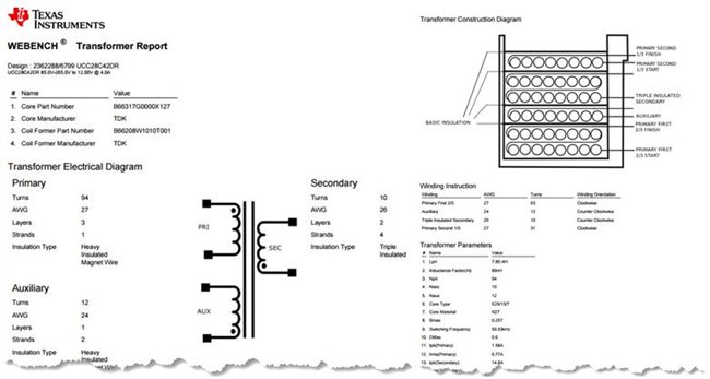 Figure 6 Transformer Design Report
Additional Resources
- Start a design in WEBENCH high voltage designer with TI’s UCC28C42 high-performance, current-mode PWM controller.
- Access thousands of power supply reference designs from the TI Designs library.
- Download “Control Challenges for Low Power AC/DC Converters” from the 2014 Power Supply Design Seminar (myTI login required).