SSZTAK7 november 2016 LDC0851 , LDC1612 , LDC1614
In my previous post, I introduced the LDC calculator tool, which you can download here. It can calculate a number of useful parameters for an Inductive Sensing application.
LDC devices use inductors to sense the movement of conductive targets. At TI, we commonly use spiral traces routed on a printed circuit board (PCB) to form sensing inductors. WEBENCH® Coil Designer is a useful online tool that can help you design a sensor inductor and also generate a layout.
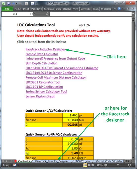
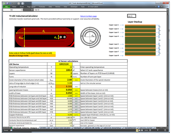
The racetrack inductor designer tool is another useful designer in the LDC tools spreadsheet. While the racetrack inductor designer only calculates sensor parameters and does not generate a layout, it is quick to use. Simply click Racetrack Inductor Designer on the Contents tab of the LDC calculator tool, or click the Racetrack_Inductor_Designer tab, as shown in Figure 1. You’ll wind up on the tab shown in Figure 2.
 Figure 1 Accessing the Racetrack
Inductor Designer
 Figure 2 Racetrack Coil Designer
Tool
Figure 2 Racetrack Coil Designer
ToolThe LDC calculator tool is pretty accurate – typically a physical sensor will be within 10% of the calculations. For racetrack-shaped sensors, however, the accuracy may degrade when the ratio of the long side to the short side is greater than 4.
The first step in the process to design a sensor is to determine the PCB manufacturing limitations. Table 1 shows an example of limits from one PCB manufacturer.
| Sensor Parameter | Value | Comments |
|---|---|---|
| PCB minimum trace width/space | 0.125 mm (5 mil) | Fabrication limitation |
| Via minimum pad size | 0.6 mm (24 mil) | Fabrication limitation |
| Via minimum hole size | 0.25 mm (10 mil) | Fabrication limitation |
| Sensor minimum inner diameter | 0.825 mm (21 mil) | 0.6 mm + 2 × 0.125 mm One via pad + two trace spaces |
| Stack-up thickness between layers | 0.80 mm (32 mil) | Desired PCB thickness |
| Copper thickness | 0.5-1.0 oz-Cu |
You now need to know a few system limitations – what is the maximum possible size of the sensor, and how close the target can be to the sensor. I’ve summarized the values for an example system in Table 2.
| Sensor Parameter | Value | Comments |
|---|---|---|
| Maximum sensor diameter | 9mm (315mil) | Mechanical constraint |
| Target closest distance | 1.8mm | Based on system mechanicals |
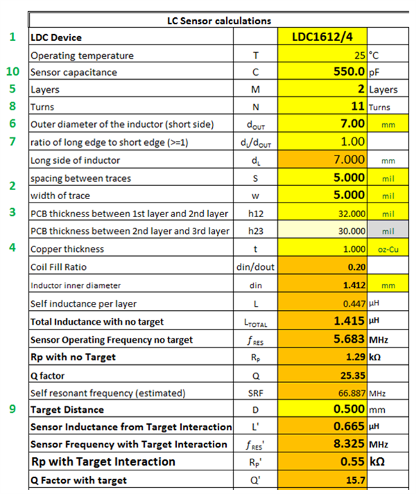
For this example, I will use the LDC1612 and comply with the limitations from Table 1 and Table 2. Figure 3 shows the calculating region of the racetrack coil designer. I placed a number to the left of each parameter so you can follow me as I walk through each setting below.
 Figure 3 Sequence to Enter
Parameters
Figure 3 Sequence to Enter
ParametersNext, follow these steps to calculate a basic sensor design:
- Select the appropriate LDC device – for this application, the LDC1612/4 (the LDC1612 and LDC1614 share the same limitations on sensor drive).
- Set the spacing between traces and the width of traces to the 0.125 mm (5 mil) manufacturer’s minimum.
- Set the spacing between layers to 32 mil.
- Use 1oz-CU, which is the thickest copper available, for better performance.
- Set the number of layers – usually two or four. Since this PCB is going to be two layers, set the number of layers to two.
- Enter the outer diameter of the inductor – 9mm is the maximum size for this example.
- Set the ratio to 1.0 for a circular-shaped sensor. Values larger than 1 will have a racetrack shape. The racetrack shape has higher inductance but a lower Q than a circular sensor. For many applications like Metal Touch buttons, a racetrack shape fits the available area better and enables smaller buttons than a circular sensor.
- Set the number of turns. If you set it to more than 16 turns, you will be below the minimum inner diameter of 0.825mm from Table 1. If you set the number of turns to 13, the coil fill ratio is close to the optimum value of ~0.3. (The 0.3 coil fill ratio is optimal for most applications, although Metal Touch applications perform better with lower values.)
- Calculate the effect of the target on the sensor by setting the distance to the target. Set the target distance to 1.80mm, which is the spacing between the sensor and the metal surface.
- Adjust the sensor capacitor to so that fRES’, RP’, and Q’ are within the LDC1614’s design space constraints. The calculator tool will indicate any parameters that are outside the design space with a red warning label on the appropriate parameter, as shown in Figure 4.
 Figure 4 Example Error Warning
Generated by the Calculator Tool
Figure 4 Example Error Warning
Generated by the Calculator ToolAfter entering your numbers, you may need to adjust the number of turns or the sensor capacitance. After trying several settings, I wound up with the values shown in Table 3. I chose 130 pF for the sensor capacitor so that I could safely use a 10% tolerance part.
| Sensor Parameter | Value |
|---|---|
| Sensor capacitance | 130 pF |
| Layers | 2 |
| Turns | 14 |
| Outer diameter | 9.0 mm |
| Ratio of long edge to short edge | 1 |
| Spacing between traces | 5 mil |
| Width of trace | 5 mil |
| PCB thickness | 32 mil |
| Copper thickness | 1.0 oz-Cu |
Because the sensor’s electrical parameters change when the target is close, you need to verify that the sensor is still within the valid operating range of the LDC when this occurs. With the closest target distance of 1.8 mm, my sensor has the electrical specifications shown in Table 4, which are within the LDC1614’s operating region.
| Sensor Inductance from Target Interaction | L' | 2.380µH |
| Sensor Frequency with Target Interaction | fRES' | 9.049MHz |
| Rp with Target Interaction | RP' | 4.90kΩ |
| Q Factor with Target | Q' | 36.3 |
The LDC tool spreadsheet has a lot more uses. In my next post, I’ll review the LDC0851 calculator tab.
Additional Resources
- Check out the “Sensor Design for Inductive Sensing Applications Using LDC”.
- To learn more about metal touch applications, download the “Inductive Sensing Touch-On-Metal Buttons Design Guide.”
- Read other inductive sensing blog posts.