SSZTAF9 February 2017 UCD90160A , UCD90240 , UCD90320 , UCD9090A
The input voltages (rails) powering today’s complex field-programmable gate arrays (FPGAs), application-specific integrated circuits (ASICs), digital signal processors (DSPs), central processing units (CPUs) and microcontrollers (MCUs) must be sequenced on and off in a controlled manner. For example, TI’s digital PMBus sequencers can control 10 to 32 voltage rails to ensure correct power-on and power-off sequences. Using the fault log and unique black-box logging function for debugging, the sequencers also monitor overall system health to help plan for both unexpected system power events and log system events. Here are some common questions and answers about initialization and sequencing for TI’s UCD90xxx sequencer family.
Q: How do I communicate with UCD90xxx devices? Is any hardware required?
A: UCD90xxx devices use PMBus communication. UCD90xxx devices are PMBus slaves, so you need to have a PMBus host to communicate with them. This PMBus host can be a microcontroller unit (MCU) or FPGA implementation that is PMBus Rev. 1.2 compliant. For ease of use, you can take advantage of TI’s Fusion Digital Power™ designer graphical user interface (GUI), which does require a USB-to-general-purpose input/output (GPIO) adapter to connect between the PC and the device.
Q: Why should I use the Fusion Digital Power designer GUI?
A: The Fusion Digital Power designer GUI serves three major functions. It:
- Provides a graphical interface to configure the UCD90xxx device so that you don’t have to waste time learning the full PMBus commands supported.
- Generates configuration files and scripts for manufacturing.
- Delivers live telemetry data for monitoring and debugging.
Q: How do I know which PMBus commands are supported by the different devices in the UCD90xxx sequencer family?
A: Since these devices support a wide range of PMBus commands, TI prepared a user’s guide. The “UCD90xxx Sequencer and System Health Controller PMBus Command Reference” provides details about the supported commands, as well as a description of the device behavior of each function.
Q: How many rails can each UCD90xxx device support?
A: The UCD90xxx sequencer family can support from 10-32 rails. However, some UCD90xxx devices have more analog monitor (MON) pins than the number of rails it can support. You can assign these additional MON pins as current- or temperature-sense pins. For example, the UCD90320 is a 32-rail PMBus sequencer that supports 24 analog rails and eight digital rails (monitoring power good signal only).
Q: What if I have to use my own PMBus host?
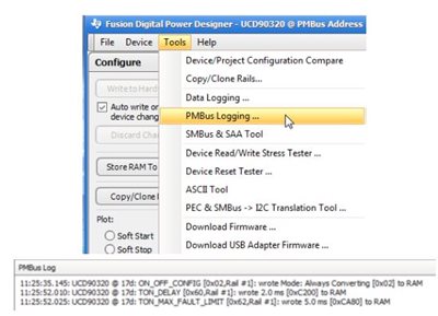
A: The Fusion Digital Power designer GUI has a PMBus logging feature to assist you. As you can see in Figure 1, the PMBus logging feature generates a text file that records all of the background communication activities between the GUI and the device. You can use the log to learn how to develop your own PMBus host.
 Figure 1 PMBus Logging Feature
Q: How can I configure and sequence the voltage rails?
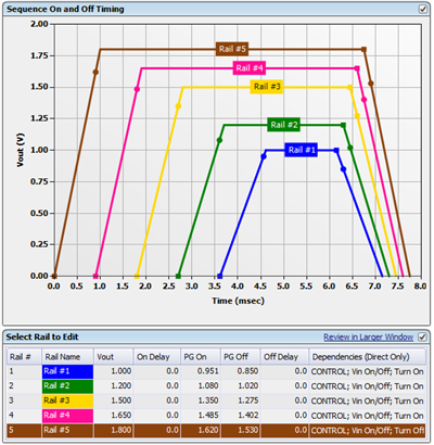
A: You can configure rail sequencing using the VOUT Config tab of the Fusion Digital Power designer GUI. When a rail receives a turn-on or turn-off command as defined in the on/off config section, it checks the dependency conditions. Once all dependencies are fulfilled, the rail then waits for a turn-on delay time or a turn-off delay time, and then asserts or de-asserts the EN pin. After the EN pin of a rail is asserted, if the rail voltage does not rise above the power good on threshold within the maximum turn-on time, a “time on max” fault occurs. During turn-off, a “time off max” warning occurs if the voltage does not fall below 12.5% of the nominal output voltage. After you’ve configured the rail sequence, the GUI displays the simulated sequence timing in the VOUT Config tab demonstrating the dependencies among the rails. Figure 2 shows an example of power-on and power-off slew rates.
 Figure 2 Sequence on and off Timing
Window (Rail Config)
Figure 2 Sequence on and off Timing
Window (Rail Config)Q: What are the different ways to sequence multiple voltage rails?
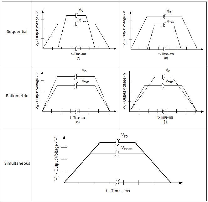
A: As shown in Figure 3, the devices can implement sequential, ratiometric and simultaneous sequencing between multiple rails, with delay or dependency-based modes programmable via PMBus.
 Figure 3 Sequencing Schemes for
Multiple Voltage Rails
Figure 3 Sequencing Schemes for
Multiple Voltage RailsQ: Can I passcode-protect my configurations?
A: Yes, the UCD90xxx has a security feature to protect against unintended/unauthorized flash writes. You can enable the security feature by using the Fusion Digital Power designer GUI, as shown in Figure 4, or by sending a corresponding PMBus command. For safety reasons, the passcode is not stored in the project file (.xml).
 Figure 4 Enabling the Security Feature
in the Fusion Digital Power Designer GUI
Figure 4 Enabling the Security Feature
in the Fusion Digital Power Designer GUIQ: Can I cascade multiple devices for higher rail sequencing?
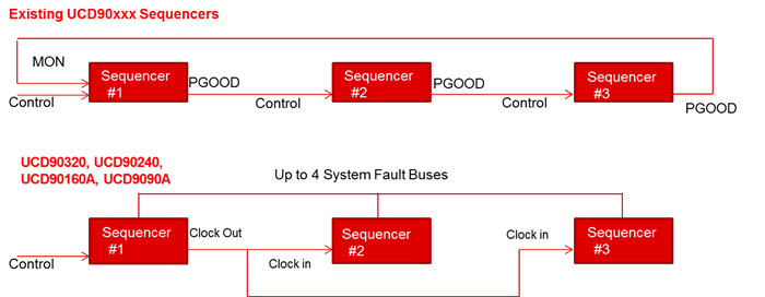
A: Cascading multiple devices is easier with TI’s newest UCD90320, UCD90240, UCD90160A and UCD9090A sequencers. With these devices, you can easily cascade multiple devices using the fault pin. There are up to four dedicated system fault pins, which can coordinate synchronized fault responses and shut down upon any rail fault. The synchronized clock enables precise timing of events on different ICs. See Figure 5.
 Figure 5 Cascading Multiple UCD90xxx
Devices
Figure 5 Cascading Multiple UCD90xxx
DevicesTI’s UCD90xxx sequencers have several features for sequencing, monitoring, margining and configuring. If you have any additional questions, please submit them in the TI E2E™ Community Sequencers forum.
Additional Resources
- Visit TI’s digital PMBUS sequencer portal.