SSZTAD2 march 2017
According to the U.S. Energy Information Administration, the average retail price for energy in the U.S. in 2014 was 10.44 cents per kilowatt hour, and estimated transmission and distribution losses were 5%. That seems pretty low until you consider that the total net generated power in the U.S was 4.1 trillion megawatt hours. A 5% loss in that case translates to over 200 billion kilowatt hours and a loss of US$21 billion, thus making efforts to improve how we transmit power a high priority.
One of the solutions implemented to reduce transmission and distribution losses is high-voltage DC (HVDC) transmission. Why is HVDC more efficient than regular AC transmission? HVDC transmission lines can have 30-50% fewer losses than AC lines with the same voltage. HVDC can improve the power factor when the voltage and current become out of phase. Because DC has no frequency associated with it, it does not suffer from skin effect, which can lower the overall power transported through the wire. Skin effect occurs when the current density concentrates at the surface, or the “skin,” and becomes less dense as it moves toward the center of the conductor. Having a higher current density along the surface creates a higher effective resistance for AC. HVDC also improves network reliability. Certain types of HVDC stations can help stabilize asynchronous networks.
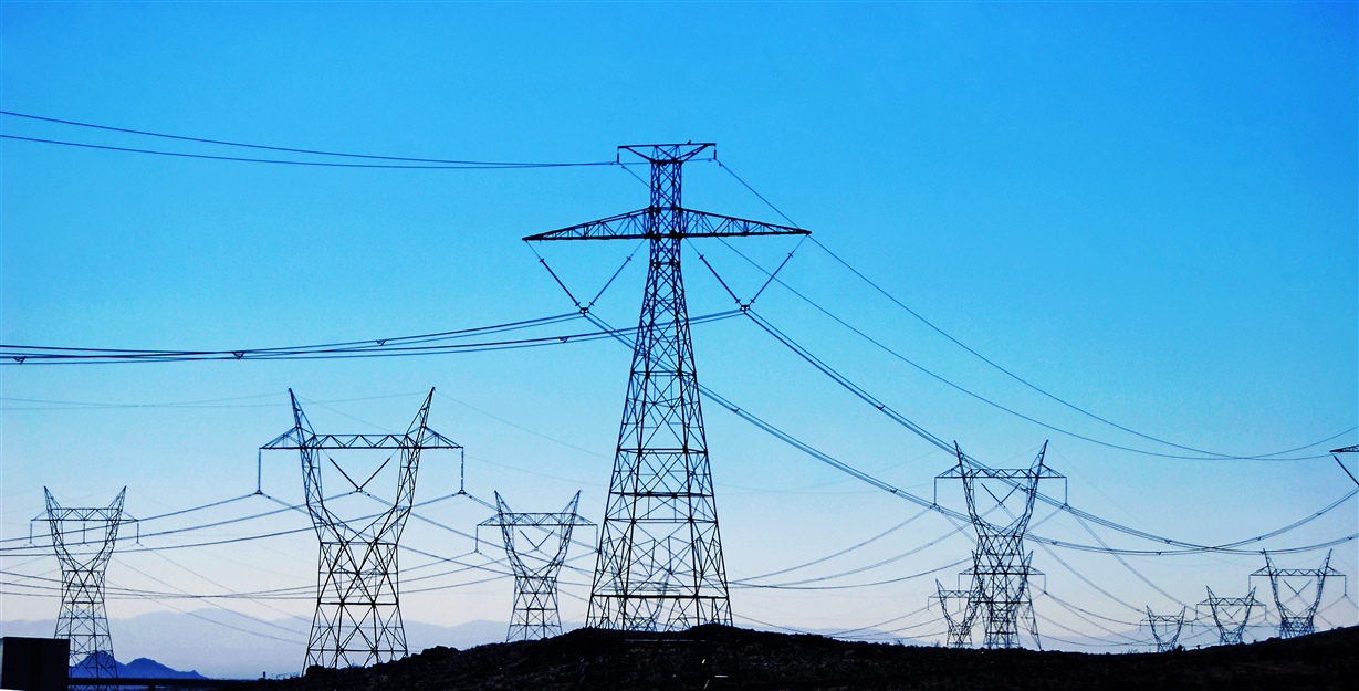
So how are such large amounts of power transported from across the country to your house? Starting from the source, they are transmitted to a converter station, where the AC is stepped up to the desired voltage before being rectified to a DC voltage. The power is then transferable over long distances as HVDC to another conversion station, where it is inverted back to AC, with the added benefit of controlling active and reactive power for certain types of converter stations. Transformers then bring the AC power up to the required voltage for transmission and distribution to homes and/or factories as needed. Figure 1 illustrates the process.
") Figure 1 Transmission Process(image
Courtesy of Duke American Transmission Lines)
Figure 1 Transmission Process(image
Courtesy of Duke American Transmission Lines)The most common types of converter stations are line-commutated converters (LCCs) and voltage-source converters (VSCs).
Lccs
The majority of HVDC systems in operation today use the LCC topology. LCCs are slightly more efficient than VSCs and are capable of transferring larger amounts of power. Their typical voltage levels are 450kV or 500kV; however, several 800kV lines exist in China. LCCs do not suffer from the switching losses that some VSCs experience because of pulse-width modulation (PWM). LCCs use thyristors as switching units. Numerous thyristors placed in series for a single branch of a three-phase rectifier make up what is known as a “valve.”
Since thyristors can only turn on, not off, the AC voltage enables the thyristors to reverse-bias and stop conducting. For this reason, thyristors in an LCC are dependent on power on the AC side of the grid for commutation. The time delay when turning on the thyristor after it is forward-biased determines the phase-angle delay (firing angle). The phase-angle delay of the thyristor implements the phase-angle control of the AC wave.
LCCs have two typical architectures: the six-pulse bridge and 12-pulse bridge. Figure 2 shows a six-pulse bridge, which uses six thyristor valves: two valves for each phase to conduct the positive and negative voltage forms. LCCs have very poor harmonic response. In order to compensate for this, 12-pulse bridges – created by placing two six-pulse bridges in series – can improve the harmonics.
") Figure 2 LCC Configuration(image
Courtesy of EE Web)
Figure 2 LCC Configuration(image
Courtesy of EE Web)An important part of controlling the waveform going into or coming out of the converter is analyzing the signal. Analyzing the signal appropriately lets the system know the voltage and current levels as well as the power factor, and helps determine if there are any faults on the line. Either a protection relay or intelligent electronic device (IED) can analyze the signals. This is shown in Figure 3.
 Figure 3 Signal Interpretation
Texas Instruments has several design guides that describe how signals are analyzed. The Reference Design to Measure AC Voltage and Current in Protection Relays with Delta-Sigma Chip Diagnostics discusses how the output signal can be collected from the use of a current transformer, a potential divider, or a Rogowski coil. This signal is then conditioned by isolated and non-isolated operational amplifier to increase the amplitude and rejects any common mode voltage and noise. The conditioned signal is then analyzed by an ADC. The digitized information retrieved from the ADC is passed to the MCU for interpretation. The information determined from the waveforms feeds back to the converters’ controls, which will make adjustments to the changing phase and voltage levels to maintain stability.
The second installment in this series will discuss VSCs and their advantages and compare them to LCCs.
Stay tuned for part two of this two-part blog series where we will discuss voltage-source converters (VSCs).
Additional resources:
- Learn more about TIDA-00810 design features
- Get designing with TIDA-00810