SSZTAC6 march 2017 AMC1100
The first installment in this two-part series covered line-commutated converters (LCCs). In this installment, I will discuss voltage-source converters (VSCs) and compare the two topologies.
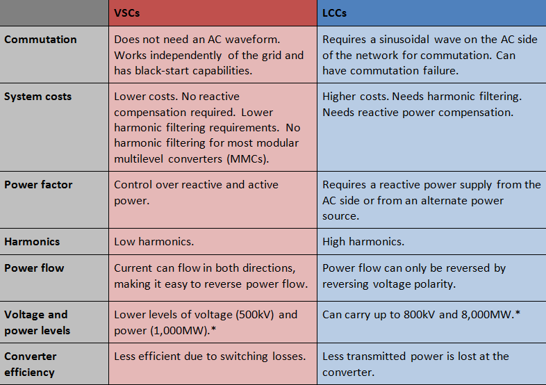
The VSC has become the preferred implementation for several reasons. VSCs have lower system costs because their stations are less complicated. VSCs enable a bidirectional flow of current, making it easier to reverse the direction of power flow. VSCs can control active and reactive power on the AC side. VSCs are not as dependent on AC networks as LCCs, so they can supply power to passive loads and have black-start capabilities. Using insulated gate bipolar transistor (IGBT) valves removes the need for commutation that thyristors require and enables a bidirectional current flow.
Table 1 compares LCCs and VSCs. VSCs have voltage levels typically in the range of 150kV-320kV, but some can be as high as 500kV. There are a few different types of VSCs. Let’s look at two-level, three-level and modular multilevel.
|
*See the 2016 Institute of Electrical and Electronics Engineers (IEEE) 16th International Conference on Environment and Electrical Engineering Conference article, “A review of LCC-HVDC and VSC-HVDC technologies and applications.”
Two-level VSCs
A two-level VSC, shown in Figure 1, will have IGBTs, each with an inverse diode parallel to it. Each valve comprises numerous IGBT/diode components in series. The IGBTs will be controlled using pulse width modulation (PWM) to help shape the wave. Because the IGBTs switch on and off numerous times while implementing PWM, switching losses do occur and harmonics are a factor.
") Figure 1 Two-level VSC(image Courtesy
of Wikipedia HVDC Converter)
Figure 1 Two-level VSC(image Courtesy
of Wikipedia HVDC Converter)Three-level VSCs
A three-level VSC, shown in Figure 2, improves the harmonics problem. A three-level converter will have four IGBT valves for each phase. Two diode valves are used to clamp the voltage, but you can replace them with IGBTs for more controllability. Turning on the top two IGBTs obtains the upper voltage level, turning on the middle two IGBTs obtains the middle (or zero) voltage level, and turning on the bottom two valves obtains the lower voltage level.
") Figure 2 Three-level VSC (Image
Courtesy of Wikipedia HVDC Converter)
Figure 2 Three-level VSC (Image
Courtesy of Wikipedia HVDC Converter)Mmcs
An MMC is different than the other two converters because each valve is a converter module with an included smoothing capacitor. Instead of a valve containing lots of IGBTs, an MMC has numerous converter modules cascaded. Each one of these modules represents a particular voltage level. The converter module in an MMC is either a half-bridge or full-bridge converter.
") Figure 3 Modular Converter Type(image
Courtesy of Wikipedia HVDC Converter)
Figure 3 Modular Converter Type(image
Courtesy of Wikipedia HVDC Converter)The MMC method significantly improves harmonic performance to the point that filtering is normally not necessary. It is also more efficient than two- and three-level VSCs because it does not have the same switching losses from the IGBT valves.
") Figure 4 Waveform Output (Image
Courtesy of SVC plus VSC Technology)
Figure 4 Waveform Output (Image
Courtesy of SVC plus VSC Technology)To monitor the power factor, voltage and current levels, the signal is measured measurable on both the AC and DC sides of the station. Upon receiving this information, the converter controls can make the required adjustments to maintain a steady power level and the appropriate power factor. A protection relay system or intelligent electronic device (IED) gathers signal information. This is shown in Figure 5.
 Figure 5 Signal Interpretation
The Isolated Current and Voltage Measurement Using A Fully Differential Isolation Amplifier is a TI reference design that can measure both AC and DC signals. The design guide explains how the signal is conditioned using isolated operational amplifier to increase the amplitude and rejects any common mode voltage and noise. A MCU with onboard ADCs will analyze and interpret this signal. The information determined from the waveforms feeds back to the converters’ controls, which will make adjustments to the changing phase and voltage levels to maintain stability.
Additional resources:
- Learn more about HVDC systems
- Start designing with the Isolated Current and Voltage Measurement Using A Fully Differential Isolation Amplifier (TIDA-00555)
- Read the first installment of this two part series