SSZTA95 April 2017 CC1120 , CC1190 , MSP430FR5994
Now that we’ve discussed smart sensing in relation to glass break detector, in part two of this series, I’ll discuss another type of application: fault indicators.
A fault indicator is a device widely used in electric power distribution networks on overhead lines and underground cables to detect and indicate fault conditions. At the bottom of a fault indicator installed on an overhead power line is a light-emitting diode (LED) light. The LED turns on when there is an overcurrent condition, thus making the failure visible to field crew members at a distance so that they can identify the point of failure.
When properly installed, fault indicators reduce operating costs and service interruptions by providing information about a failed section of the network. At the same time, the device increases safety and reduces equipment damage by reducing the need for hazardous fault-diagnostic procedures. Fault indicators, due to their location, are primarily battery-powered; thus, low-power operation is highly desirable.
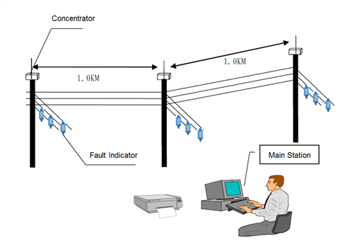
Recent developments in ultra-low-power microcontrollers and wireless connectivity technology have enabled the development of “smart” fault indicators. Figure 1 illustrates an example of a smart fault-indicator system.
 Figure 1 A Smart Fault-indicator
System
Figure 1 A Smart Fault-indicator
SystemIn Figure 1, the fault indicators are installed on the junctions of the overhead power-line network. Fault indicators send measurement data about the temperature and current in power transmission lines wirelessly to the concentrator/terminal units mounted on the poles. The concentrators use a Global System for Mobile Communications (GSM) modem to pass the data to the cellular network to relay real-time information to the main station. The main station can also control and run diagnostics on the fault indicators through this same data path. For underground cables, the fault indicators are connected to the concentrator through a wired network such RS-485.
Connecting to the main station at all times has several advantages. The first is the ability to remotely monitor fault conditions from the main station. The crew members from the utility company do not need to go in the field to find the fault location. A smart fault indicator is also capable of constantly monitoring temperature and current so that the controller at the main station has real-time status information about the power distribution network. With these additional pieces of information, power utility providers can quickly identify the fault location, minimize power downtime and even take action before a failure occurs. Workers at the main station can run diagnostics on the fault indicators at required intervals to make sure that they work correctly.
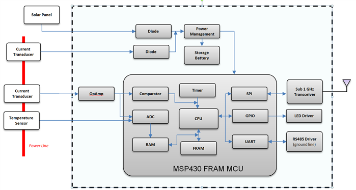
Figure 2 is a functional block diagram of a smart fault indicator based on the TI MSP430™ ferroelectric random access memory (FRAM) microcontroller (MCU). The current transducer produces an analog voltage proportional to power-line current. An operational amplifier (op amp) amplifies and filters this voltage signal. The analog-to-digital converter (ADC) on the MCU samples the output of the op amp. The digital stream from the ADC is then analyzed by software running on CPU or accelerator. The op amp output is also connected to a comparator on the MCU. The comparator generates a flag to the central processing unit (CPU) in the MCU if the input level is beyond a predetermined threshold.
 Figure 2 Functional Block Diagram of a
Smart Fault Indicator Based on the MSP430 FRAM MCU
Figure 2 Functional Block Diagram of a
Smart Fault Indicator Based on the MSP430 FRAM MCUCurrent-measurement analysis can occur in the time domain or the frequency domain. Enabled by the computing power of a new generation of MCUs, frequency-domain analysis has become more popular for these reasons:
- When the current waveform on the power line is far from a sine wave and waveform irregularity is a concern, spectrum analysis is a straightforward method for harmonic analysis, providing a more complete evaluation of line status.
- With the development of distributed generation, some applications require that the fault indicator detect the direction of the fault current. Recent research indicates that you can estimate the direction of current by continuously monitoring current amplitude and phase. Conventional technology requires expensive equipment to monitor voltages.
Assume that the frequency of interest to detect transients in a power-line current is from DC to 10kHz. To meet this requirement, set the analog-to-digital sample frequency to 25.6kHz and use the fast Fourier transform (FFT) algorithm to collect blocks of data over every 20ms interval. With this setting, a 512 real-point FFT can generate a spectrum up to 12.8kHz with 50Hz resolution. The FFT output will be fed to a pattern-recognition algorithm to check the line status.
As I mentioned in the first installment of this series devoted to glass break detectors, the MSP430FR5994 MCU solves this math-performance and power-consumption conflict by integrating the low energy accelerator (LEA) peripheral. It takes the LEA only about 1ms for the 512 real-point FFT when running at 16MHz.
Considering the overheads of data movement and windowing, you will need an additional 0.5ms of LEA time and 0.5ms of CPU time. For each 20ms interval, 19.5ms of CPU time and 18.5 of LEA time are available for pattern recognition and other system functionalities.
The MSP430FR5994 has 256KB of FRAM. The fast read-and-write speed of FRAM enables the accumulation of data for pattern analysis. The MSP430FR5994 MCU also has a direct memory access (DMA) module, which can move data from peripherals such as the ADC to memory, or from memory to memory, without CPU intervention. The 12-bit ADC on the MSP430FR5994 can run up to 200KSPS. It provides more than enough performance for this application.
Line temperature is also an important data point related to power-line health. The temperature sensor output is normally a voltage that the ADC on the MCU can sense directly.
After processing is complete, the fault indicator sends the output data to the concentrator through a wireless link. Sub-1-GHz connectivity technology achieves the required transmission distance while minimizing power consumption. For ground lines, the data can be output to an RS-485 interface. The MCU may need to encrypt the data based on the system’s security requirements. The MSP430FR5994 has a hardware accelerator to support Advanced Encryption Standard (AES)-128 and AES-256. A traditional LED light will turn on when the fault indicator detects a failure condition.
A fault indicator is a battery-operated device installed on either overhead power-transmission lines or underground power cables. Access is very limited once installed. Therefore, it is critical for fault indicators to have a long battery life.
These two steps can help minimize the power drawn from the battery:
- Take advantage of low-power MCU modes. The MCU can be put into low-power mode when data processing is not needed. Using the LEA gets signal processing done quickly, and the CPU can also go into low-power mode when idle.
- Use energy harvesting. The functional block diagram in Figure 2 shows two possible sources for energy harvest: a solar panel and a power transmission line (via a current transducer).
TI also provides solutions for energy harvesting and wireless communication. Please refer to the information in the additional resources section for more details.
Additional resources:
- Download our white paper about setting a new standard for MCU performance
while minimizing energy consumption.
- Learn how the LEA module can be used in smart fault indicators in this white paper.
- Read our other blog posts about MSP430F5994 MCUs:
- Check out TI’s wireless communication and energy harvest solutions:
- More information about fault indicators: