SSZTA64 may 2017 TPS543B20 , TPS543C20
Internally compensated advanced current mode (ACM) is a new control topology from Texas Instruments that supports true fixed-frequency modulation and synchronization with internal compensation. Fundamentally, it is similar to emulated peak-current-mode (PCM) control, which maintains stability over a range of input and output voltages for fast transient response. What makes ACM different is that it is a ramp based, peak current mode control scheme that internally generates a ramp to achieve true fixed frequency, without using external compensation. As well, ACM has good immunity for power-stage (inductor and capacitor) variation, but I will go into more details on the virtues of ACM here.
Why internally compensated ACM?
There are control topologies that support either true fixed frequency or pseudo fixed frequency without the need for an external compensation network. However, there are some drawbacks to using these.
Most existing true-fixed-frequency/no external compensation converters are based on traditional peak current mode, which moves the compensator from outside the package to inside the circuitry, with the internal compensator designed and optimized to cover a variety of applications. Because the internal compensation needs to cover a variety of stability ranges, the internal loop and slope compensation are very difficult to optimize if you need to achieve a fast transient response. The loop bandwidth must also be limited to accommodate wide application cases. Usually, you will see a very slow transient response, especially during large-load-current step changes.
There are also control topologies with a constant on-time modulator that maintain a pseudo fixed frequency without external compensation, like TI’s D-CAP™/D-CAP3™ control mode. The on-time is fixed for certain VIN and VOUT and the switching frequency can vary during load transient, which gives very good transient performance. However, this frequency variation also brings electromagnetic interference (EMI) concerns, especially for EMI-sensitive telecommunication applications. Internal compensated ACM addresses the drawbacks from both fixed-frequency and constant on-time control.
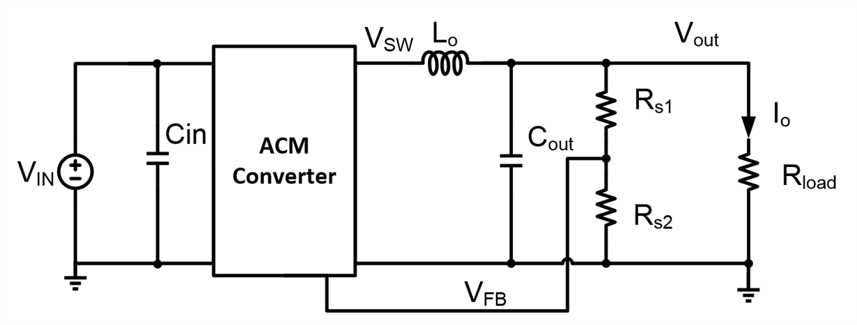
The simplified buck structure with ACM shown in Figure 1 below feeds the feedback voltage information from the output stage to the internal integrator, with no compensation network needed externally.
 Figure 1 Simplified Buck System with
ACM
Figure 1 Simplified Buck System with
ACMThe simple control structure brings the benefits of:
- A nice and easy output voltage feedback loop. It only requires RS1 and RS2 as resistor dividers to sense Vout without the compensation network, and sensed Vout information is sent back to the control loop via VFB.
- Without external components needed for PID (proportional–integral–derivative) or PI (proportional–integral) compensation, the designer avoids the complicated compensation design, which makes it very easy to use
- The elimination of external compensation components also saves component count and precious PCB real estate.
Internal Compensated ACM Control Overview
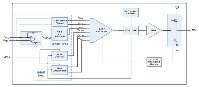
The overall block diagram of the ACM control loop is shown in Figure 2 below. ACM includes a voltage loop, ramp loop, comparator, current feedback and pulse-width modulation (PWM) logic.
 Figure 2 ACM Control Building
Blocks
Figure 2 ACM Control Building
BlocksFunction of each block:
- The voltage loop senses and processes error signals from VFB.
- Ramp loop generates a ramp voltage according to VIN and PWM signal. The slope compensation is optimized to remain at half of the down slope of the ramp voltage.
- The loop comparator adds up the input signals and terminates the PWM cycle when the sum of positive inputs reaches the sum of negative inputs.
- Current feedback also adds DC current information to optimize the Q factor of the loop.
- PWM logic generates the PWM signal according to the clock and output of the loop comparator.
Traditional PCM vs. Internally Compensated ACM
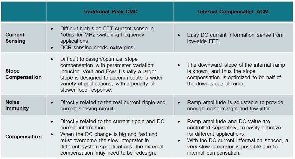
Figure 1 shows the comparison of traditional peak current mode and Internally Compensated AMC:
 Figure 3 . Traditional Peak Current
Mode and Internal Compensated ACM Comparison
Figure 3 . Traditional Peak Current
Mode and Internal Compensated ACM ComparisonConclusion
Internally compensated ACM control is a ramp based, peak current mode control scheme that internally generates a ramp to achieve true fixed frequency, without using external compensation. ACM provides better transient response than traditional peak current mode by separately optimizing both the AC and DC portions of the voltage loop and ramp loop. This control mode provides an optimized solution for applications that require predictable frequency without the need for external compensation. TI’s high-performance TPS543B20 and TPS543C20 step down converters include the new internally compensated ACM control. The converters support 25/40A with stack ability (TPS543C20 only), and include internal compensation for ease-of-use, fixed frequency for low EMI noise, and full differential sense to achieve the best VOUT set-point accuracy.
Learn more about TI’s portfolio of buck converters with integrated switches and read the “Control-Mode Quick Reference Guide” for an overview of the various non-isolated DC/DC regulator control modes offered by TI. Watch the video overview with the advantages and disadvantages of each control mode, including the new internally-compensated ACM
To discover more about this new topology, read the white paper, "Internally Compensated Advanced Current Mode (ACM)" and start designing with the TPS543C20 with the Dual-Channel, Step-Down Converter Reference Design with 97% Efficiency for Server PSU.