SSZTA37 June 2017 LM25122-Q1 , TPA3251
Are you a fan of listening to loud music while driving? I definitely am, especially on long road trips. The 700W Automotive Class-D Automotive Amplifier Reference Design shown in Figure 1 can support up to 700W true root mean square (RMS) power, which should easily be enough power to satisfy demand for loud music lovers in automobiles.
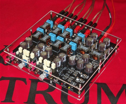 Figure 1 Built and Tested Automotive
Audio Amplifier System
Figure 1 Built and Tested Automotive
Audio Amplifier SystemThe main power supply consists of a two-phase interleaved synchronous boost converter built with two LM25122-Q1 boost controllers in a master-slave configuration. This circuit supplies two TPA3251 350W high-performance Class-D amplifiers. The input voltage range of the boost converter is 9V to 16V and generates an output voltage of 36V, with a maximum load current of 20A. The design is functional down to 6V at the input, but can only deliver about half the output power under those conditions.
One of the TPA3251 amplifier stages provides the signals for the speakers on the left and right sides of the vehicle. The maximum output power per channel is 175W for a 4Ω impedance. For the other amplifier stage, the two channels when bridged deliver 350W to a subwoofer or subwoofer array with a 2Ω impedance. Figure 2 shows a block diagram of the system.
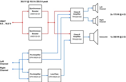 Figure 2 700W Automotive Class-D
Automotive Amplifier Reference Design Block Diagram
Figure 2 700W Automotive Class-D
Automotive Amplifier Reference Design Block DiagramFigure 3 shows the schematic of the main power supply.
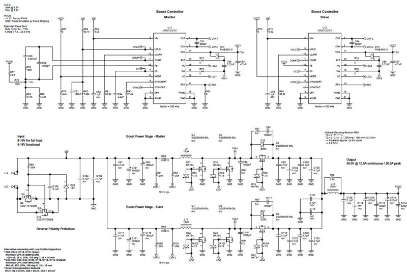 Figure 3 Power-supply Schematic
A clipping detector (Figure 4) and pre-amplifier (Figure 5) for each audio amplifier stage are also part of this design. An optional second-order active low-pass filter, built with the OPA1662A-Q1 operational amplifier, is integrated for connecting a subwoofer to one of the amplifiers. Its corner frequency is set to 80Hz in order to direct only very low frequency signals to the subwoofer.
Auxiliary power supplies generate the operational amplifier’s positive and negative supply-voltage rails for the clipping detector and pre-amplifier circuits. They have been designed with the LM2841X-Q1 DC/DC switching regulator in a buck configuration for 12V and an inverting buck-boost configuration for -12V (Figure 6).
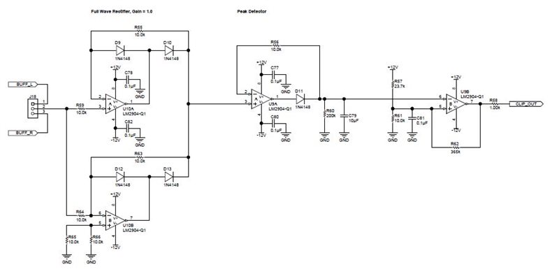 Figure 4 Schematic of the Clipping
Detector
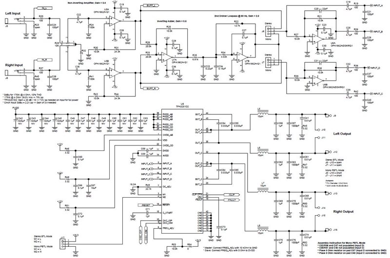 Figure 5 Schematic for One
Amplifier Stage
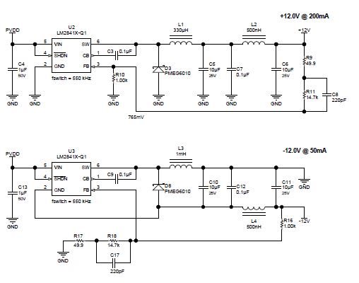 Figure 6 Schematic of Auxiliary
Power Supplies
Figure 6 Schematic of Auxiliary
Power SuppliesWith Class-D technology, the total system dimensions of 22cm by 20cm by 3cm can easily fit under the passenger seat of an automobile. Class-D not only has an advantage regarding size, but its efficiency is significantly higher compared to Class-AB, which has been commonly used in automotive audio systems in the past.
With its thin profile and high power output, this design is ideal for engineers designing car audio external amplifiers applications for automotive infotainment systems.