SSZTA03 july 2017 UCC21222-Q1 , UCC27201A-Q1 , UCC27524A-Q1 , UCC28070 , UCC28070-Q1 , UCC2813-5-Q1 , UCC28951-Q1 , UCC28C41-Q1

Electric vehicles (EVs) are an unavoidable topic when discussing modern transportation. Coming from Germany, a country that takes pride in their automotive history, the EV market is growing fast. I would consider buying an electric car in the near future, as would many others.
According to several forecasts, the market for EVs will increase dramatically, from 500,000 in 2015 up to 41 million by 2040. The global governmental growth target is even higher: 100 million electric cars and 400 million electric two- and three-wheelers on the streets by 2030.
Two of the key considerations when buying an EV are charging time and maximum range. Long charging times and the lack of an existing DC charging infrastructure are drawbacks for many potential consumers. With the rapid growth of this market also comes the rapid development of fairly substantial integrated onboard chargers (one to six hours) and fast charging piles (30 minutes).
Let’s go deeper into some definitions and characteristics of the two different charging systems: onboard chargers and fast charging piles.
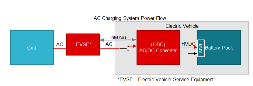
An EV or hybrid electrical vehicle (HEV) uses onboard chargers to convert line current (50/60Hz AC) to DC and to provide an isolated DC output to charge the traction battery, as shown in Figure 1.
 Figure 1 High Level System Block
Diagram- On-board Charger
Figure 1 High Level System Block
Diagram- On-board ChargerAn EV usually consists of one lead-acid battery operating at 12V and one lithium-ion (Li-ion) battery operating at a higher voltage of around 400V to 800V. The 12 V battery support loads such as infotainment, lighting, and windows, while the high-voltage battery serves as the energy source for high power loads such as the air-conditioning compressor and traction inverter.
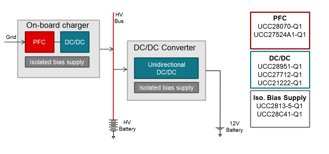
Onboard charger modules are normally two-stage converters: the input stage uses a power factor correction (PFC) module in the AC/DC power supply with a 400VDC output, which is then fed into the next stage, an isolated DC/DC converter, as shown in Figure 2. The isolated DC/DC converter provides galvanic isolation and a constant voltage and current output, which is necessary for efficient battery charging.
 Figure 2 PFC and DC/DC Controller for
On-board Charger
Figure 2 PFC and DC/DC Controller for
On-board ChargerThe unidirectional high- to low-voltage converters then charge the 12V battery from the high-voltage battery bus.
A DC charging (pile) station has the same properties as an onboard charger module except that the AC/DC PFC stage and isolated DC/DC stage are off-board and integrated into the station. The DC output bypasses the on-board charger and is fed directly to the battery as shown in Figure 3. The charging pile can deliver over 100 kW of power which enables the system to achieve significantly faster charging times than the onboard system.
 Figure 3 DC Charging Station for
EV
Figure 3 DC Charging Station for
EVBut what is PFC and why is it necessary? You can find PFC in most isolated AC/DC power supplies, where it efficiently transmits energy from the power grid to the end system. The PFC draws an in-phase sinusoidal current from a sinusoidal source. This reduces the peak and harmonic currents and maximizes the drawable power from a given AC source – a household socket, for example. Usually any electric equipment that uses 75W or more from the grid is required to use PFC.
TI’s AC/DC controller solution for both charging systems is the UCC28070-Q1 interleaved continuous-conduction-mode PFC. The UCC28070-Q1 is an advanced PFC device that integrates two pulse-width modulators (PWMs) operating 180 degrees out of phase. This interleaved PWM operation substantially reduces the input and output ripple currents, enabling easier and less-expensive conducted electromagnetic interference filtering.
The UCC27524A-Q1 is an exceptional gate driver solution for the PFC stage of an on board charger and charging pile. The high drive current allows for efficient switching of the power switch. The negative voltage handling and timing specs contribute to an extremely robust PFC stage.
The isolated DC/DC function is best implemented with a phase-shifted full bridge (PSFB) and the UCC28951-Q1 as the controller and either UCC27201A-Q1 or UCC21222-Q1 as the gate driver. The PSFB works in high-voltage and high-power DC/DC applications where the output voltage varies over a wide range, as found in battery-charging applications. Furthermore, the zero-voltage-switching action of the PSFB significantly reduces switching losses in the primary-side metal-oxide semiconductor field-effect transistors (MOSFETs), enabling potential efficiencies greater than 99%.
The choice between an isolated and non-isolated gate driver in this topology depends on the location of the controller. If the controller is located on the high voltage side, isolation may not be needed so a non-isolated driver, such as UCC27201A-Q1, can be used. If the controller is located on the low voltage side than an isolated gate driver, such as UCC21222-Q1, is an excellent way to provide the isolation for a system.
The AC/DC PFC controller, isolated DC/DC controller and gate drivers require bias power in order to operate. The flyback topology is the most popular choice of isolated DC/DC bias supply due to its low-cost, wide-input voltage range and ability to provide multiple isolated outputs. The UCC2813-5-Q1 general purpose PWM controller configured as a fixed-frequency peak current mode flyback is a superior solution because it supports a max turn-on voltage of 4.5 V enabling operation during cold cranking from 12V battery systems. For a cost-competitive alternative for systems without cold cranking minimum voltage requirement, the UCC28C41-Q1 offers pin-to-pin compatibility with a max turn-on voltage of 7.5 V.
As the market for EVs continues to expand, so will TI’s development of products to support these charging solutions. Read the blog, “Pile on to a charger – my EV needs power” to learn about the subsystems that transfer large amounts of power at EV charging stations.