SSZT994 august 2017 LM3404 , LM3409 , LM3414 , TPS92515 , TPS92640
Red, green, blue and white (RGBW) light emitting diode (LED)-based color-tunable luminaires are very common in applications such as stage lighting, entertainment lighting and architectural lighting; Figure 1 shows a couple of examples. In this blog post, we will discuss the key challenges associated with designing such LED light sources and how to resolve them.
 Figure 1 Stage and Architectural
Lighting
Figure 1 Stage and Architectural
LightingIn stage-lighting applications, which require the generation of different colors as well as dimming, individual LED strings are generally duty-cycled using a pulse-width modulator (PWM). Although the human eye cannot detect PWM frequencies of more than 200Hz, both video and still cameras can see LED on/off cycles due to the PWM. Capturing video with a complementary metal-oxide semiconductor (CMOS) sensor-based video camera and filming with the “rolling shutter” method, the video will show a dark band moving up or down in the presence of an LED light source with a lower-frequency PWM. A CMOS sensor-based still camera can cause an underexposed band to develop on the image. Such effects are not acceptable; thus, a luminaire design has to include methods that avoid this issue, while also producing excellent color mixing and an immersive user experience.
Analog vs. PWM Methods for Generating Colors and Dimming
To generate a wide range of colors, a common method is to use four LED strings for red, green, blue and white. By changing the current through the LED strings, you can generate the complete color spectrum. The easiest way to change the current is to use a programmable linear current source for each LED string. Unfortunately, this will cause huge power losses and increased thermal-management issues.
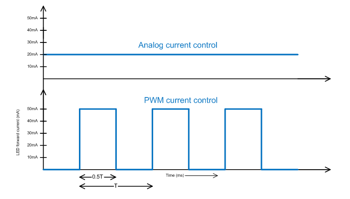
A third method is to power up each string using a PWM buck regulator or buck controller operating at a few hundreds of kilohertz, set the peak current through the LED string to its recommended operating value, and use a PWM to enable and disable the converter, thereby having the PWM modulate the current through the LED. Using this method, you can control dimming and color generation without much loss, and without changing the LED string’s color temperature. Devices such as the LM3404, LM3414, TPS92515, TPS92640 and LM3409 have a built-in PWM modulation pin that enables the modulation of LED current at frequencies well above 10kHz. Figure 2 shows the analog and PWM current control methods for LEDs.
 Figure 2 Analog and PWM Current Control
A Shunt FET Dimming Method
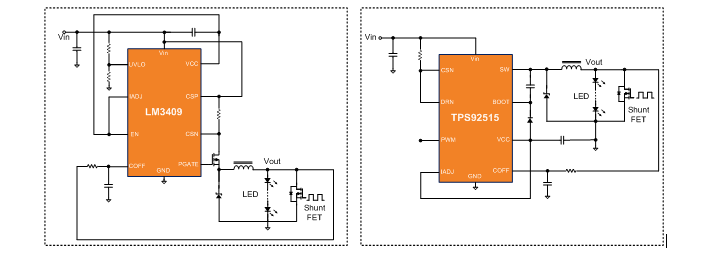
Because of delays in the shutdown and startup of a buck converter’s output, there is a limit to the PWM dimming frequency and range of duty cycles. To help overcome this delay, you can place an external shunt device such as the FET shown in Figure 3 in parallel with the LED or LED string to quickly bypass the converter’s output current around the LED(s). The current in the inductor remains continuous during the LED shutdown time, avoiding the long delay in ramping the inductor current pedestal up and down. The delay time now shifts to the limits of the shunt device’s rise and fall times.
 Figure 3 Shunt FET Dimming
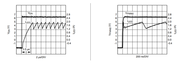
Figure 4 shows the plots comparing the LED on/off delays when using the PWM dimming function pin vs. the shunt FET. Take precautions when shunting the LED current with current-mode converters because of the overshoot in output current when the FET turns on. The LM340x family of LED drivers are quasi-hysteric and will not exhibit this overshoot. Keep the output capacitance across the LEDs low in order to maximize the on/off/on transition speed.
 Figure 4 Comparison of PWM Dimming and Shunt FET Dimming
A disadvantage to the fast shunt FET dimming circuit vs PWM dimming method is a loss of efficiency. While the shunt device is on, a power dissipation of VShunt device × ILED is lost as heat. Using low RDS(on) field-effect transistors (FETs) will minimize this efficiency loss. Overall, shunt-FET dimming allows very high frequency PWM dimming without compromising much on the dimming linearity and contrast ratio compared to standard PWM dimming for modulation frequencies above 25KHz.
In the second installment of this two-part series, we will discuss the need for high PWM frequency as well as high resolution in stage-lighting applications, along with a design in the TI Designs reference design library that helps solve system-level challenges.
Additional Resources:
- Click here to find more lighting design resources
- Check out this 100-W, High - Resolution, 16-bit Color - Tunable, 0.15% Dimmable RGBW LED Luminaire Reference Design