SSZT954 september   2017 TPS544C20 , TPS546C23


  1.   1
  2.   2
    1.     3
    2.     So, What Exactly is PMBus?
    3.     What Benefits Does PMBus Provide?
    4.     How Do You Set up and Use PMBus?
    5.     Using the PMBus GUI
    6.     Choosing Online or Offline Modes

I’m working as a product marketing engineer intern, and immediately received several tasks working with many different devices in the TI arsenal. The biggest problem I had was understanding the differences between them. One word that kept coming up (among many) was PMBus – PMBus with telemetry, PMBus without telemetry, etc. Every piece of TI support material highlighted this distinction, but what was it? After answering a few (actually many) questions, my manager asked me to research what PMBus actually was and how to use it, and write a blog post about what I learned for other people in my shoes.

So, What Exactly is PMBus?

Power management (PM)Bus is an I2C-based communication standard for power-supply management; in other words, it’s a monitoring and warning system. It’s like when a car starts making a dinging noise because your door is open or you haven’t buckled up. In PMBus, the car is the device, you are the host, and the dinging is the signal PMBus gives so that the host can decide how to respond. In a device, PMBus can monitor input/output (I/O) voltage/current, temperature, fan speed, etc.

The four types of communication between the host and device are command, control, sequence and monitor. The difference between I2C and PMBus is similar to the difference between a sentence and a language, respectively. I2C can write out commands to push through, but it is prone to many errors and is very basic. I2C is preferable if you want to transfer a lot of data, since with PMBus you have to be more specific with commands. This need to be explicit enables more complex commands, along with error prevention.

What Benefits Does PMBus Provide?

Since PMBus can monitor many different parameters in real time, you can program the device to react to certain parameters in a way that will increase efficiency and reliability while decreasing power consumption, which translates to cost savings. The basic form of PMBus has adaptive voltage scaling (AVS) (reduced power usage), multiple rail control (supply sequencing) and power-supply monitoring capabilities. AVS allows you to measure values such as temperature and pressure and use that information for optimizing power, current or voltage. Telemetry is the function of converting the measured information into binary data for optimization and analysis.

How Do You Set up and Use PMBus?

TI has a huge variety of devices that include PMBus and are coming out with new ones every day, like the TPS546C23. For this post, I was able to sit down and use a TPS544C20. To program TI’s PMBus devices, there are Fusion Digital Power™ graphical user interfaces (GUIs) designed to help engineers program and design the chips to their exact specifications. Let’s look at how.

Using the PMBus GUI

Make sure to download the correct GUI. There are three different types designed for different functions: Fusion Digital Power Designer, Fusion Digital Power Studio and Fusion Digital Power Manufacturing.

Fusion Digital Power Designer is the original GUI, and is used for low-voltage and multiphase parts. Designed for engineers trying to configure and monitor devices used in projects, this GUI supports power products, including the UCD9xxx and TPS5xxx families, and is the only tool for configuring devices without having to code.

Fusion Digital Power Studio, a branch off of the original GUI, does the same monitoring and configuring to design devices into projects. The difference is that this GUI supports power products, where coding is necessary. The tool is much simpler than the original, and is a debugging tool. It’s designed for use in conjunction with TI’s Code Composer Studio™ integrated development environment (IDE), or other ARM processor IDEs.

Fusion Digital Power Manufacturing is a simplified version of the GUI and has only three buttons. It is usually used for production, with no built-in debugging features. The GUI programs supported devices to the specified configuration.

For this post, I will be using Fusion Digital Power Designer.

Choosing Online or Offline Modes

Use online when you have a physical device to configure and want to see a real-time response. This is usually when debugging, or in my case, when you just want to mess around with a prototype. If you are using a physical board to program, go ahead and connect it. To start, plug the USB/I/O cord into your device and then into your computer (there will be a small green light-emitting diode [LED] that turns on, indicating that the adapter is connected). From there, attach the ribbon cable to the I/O port of the board, paying attention to the grooves on the connector. Last, plug the power source in. When you open the GUI, it should recognize that a device is connected.

Use offline when you do not have the actual device, but still want to see what the response will be. This is very useful when designing and getting ahead on projects, or simply evaluating which device is the best fit for your system.

After you open the application, the screen shown in Figure 1 will appear. Chose Offline Mode if you do not have a physical device. If you have a physical device, make sure to connect it and select retry and skip.
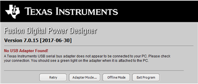
GUID-7408FF88-A19A-4267-B623-4022C8D750CE-low.png Figure 1 Opening Window

Select the first option to start a new project from scratch (Figure 2).

GUID-75512B96-1132-44EE-8ABE-C71F1CAB7EAB-low.png Figure 2 Project Selection

Since you are offline, you need to select the device you want to program (Figure 3).

GUID-ECAC17A5-5BC3-459F-B341-62CCCAD99C15-low.png Figure 3 Device Selection

Make sure to select one of the three options listed in Figure 4 to make the list of devices in those sections appear. Once you’ve selected a device, press OK and Finish.
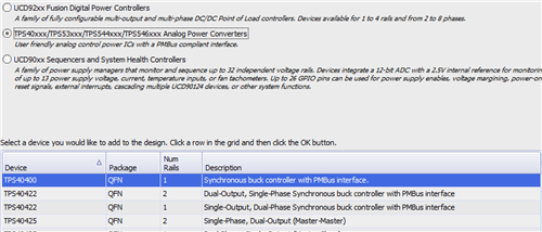
GUID-A55F081D-36CA-458A-B1FB-5A53AAF910AF-low.png Figure 4 Device Category Selection

You have now arrived at the home page of the GUI. If you have a physical device and are in online mode, Figure 5 should be your initial landing page. From here, you can configure the device. Click Start Polling to see how the device reacts to the configurations.

GUID-541F6DAD-4192-49E9-B603-F40FDDB87988-low.png Figure 5 Main Page

To navigate, use the tabs in the lower left-hand side of the screen shown in Figure 6. When you have changed something, make sure to Write to Hardware by using the button in the upper left-hand side of the screen. To save the configuration, use the Store Config to NVM button.
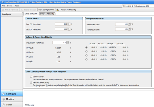
GUID-B7A63267-C27C-4FA8-A144-398CB07C3B81-low.png Figure 6 Control Window

When I first sat down to look at how to use the PMBus and GUI, I was a little overwhelmed. I hadn’t even opened the package and I was imagining the complicated software I would need to learn to configure the device. After I had a chance to sit down and play with the PMBus and GUI, I realized that it was quite simple to set up and use, almost a plug-and-play type of equipment. What has your experience been using PMBus for the first time?