SSZT947 september 2017 TPS54302 , TPSM84203 , TPSM84205 , TPSM84212
Designers have used linear regulators for decades in electronic applications because of their simplicity and low cost. For a complete step-down power supply, you only need an input and output capacitor along with a linear regulator, which is much simpler to design and has lower noise when compared to a switching regulator. In applications where the input voltage (VIN) is close to the output voltage (VOUT), its efficiency is also high. Because of these advantages, you’ll still find linear regulators used as regulators in low-power systems.
Among the available linear regulators in the market, the UA7805 family is very popular – it comes with fixed output voltages and is typically available in a standard three-pin transistor outline (TO)-220 package (Figure 1). The three pins are VIN, VOUT and GND. A good example is the UA7805, which features a fixed 5V output and benefits from the advantages I listed above. The UA7805 does have an obvious disadvantage in applications where the input voltage is high, however: large power dissipation.
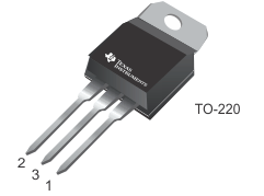 Figure 1 3-Pin to-220 Package
During operation, the output current is equal to the input current. The internal metal-oxide semiconductor field-effect transistor (MOSFET) mostly works in its saturation region while managing the voltage drop between the input and output voltage. The power loss for the UA7805 is (VIN-VOUT)*IOUT, which for a 12V input voltage and 5V output voltage with only 200mA of output current represents a power loss of 1.4W ( (12V-5V)*0.2A).
That 1.4W turns into heat, which dissipates through the case and the air. Figure 1 is the case temperature for the UA7805 under 12V to 5V with 200mA output current. Without a heat sink, the case temperature could rise as high as 103.1°C. When taking the thermal resistance from junction to case into account, the internal die temperature is even higher. The TO-220-packaged UA7805 supports output currents of up to 1.5A, but under 12V-to-5V conditions, the UA7805 must significantly limit its output current. With higher input voltages (such as the popular 24V supply), this linear regulator becomes unusable due to thermal issues. Figure 2 is the case temperature for the UA7805.
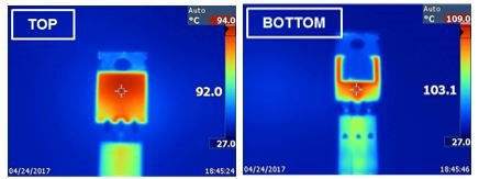 Figure 2 Case Temperature for the
UA7805 under 12V to 5V/200mA
Figure 2 Case Temperature for the
UA7805 under 12V to 5V/200mAFor 12V and 24V power bus applications, buck switching regulators are more suitable, as they have better efficiency and thermal performance. The internal power MOSFETs will work in their linear region; only conduction and switching losses will contribute to the device’s power dissipation. Under the same working conditions, the total loss for a buck regulator is much less than for a linear regulator. So if it is possible to upgrade the TO-220-packaged UA7805 with a higher-efficiency buck regulator, you can greatly improve the overall energy efficiency of your system.
There are several challenges if you choose a switching buck regulator to replace the UA7805:
- More design complexity. Designing a buck regulator requires selecting components such as a filter inductor and capacitors. Tuning control loops also requires a strong power and control background.
- Higher bill-of-materials (BOM) count. Most buck regulator integrated circuits (ICs) are either controllers or integrated converters. You will need power FETs, an inductor and capacitors.
- New printed circuit board (PCB) layout design. Most switching buck regulator ICs are surface-mount, and you will need to reroute the PCB layout to replace the UA7805.
- Possible electromagnetic interference (EMI) issues. A switching regulator can cause noise and EMI issues due to fast switching speeds.
To meet these challenges, TI has released a new buck power module family – the TPSM84203/05/12– developed with the TPS54302 DC/DC converter IC. This family comprises three devices (the TPSM84203, TPSM84205 and TPSM84212) capable of delivering up to 1.5A from a 24V supply (28V max) and providing fixed output voltages of 3.3V, 5V and 12V, respectively.
The regulator IC, inductor, input bypass capacitor and boot capacitor are all integrated into a module. Like the UA7805, there is no need for component selection except for the input and output capacitors. The three-pin (VIN, VOUT, GND) TO-220 package offers pin-to-pin compatibility with the UA7805 and thus provides a significant efficiency improvement without any board change. Figure 3 shows the TO-220 package interior for the TPSM84203/05/12.
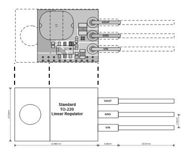 Figure 3 Same to-220 Package for the
TPSM84205 and UA7805
Figure 3 Same to-220 Package for the
TPSM84205 and UA7805Figure 3 compares the efficiency and power loss of the TPSM84205 and UA7805. One nice feature of the TPSM84205 is that its light-load-efficiency mode keeps the efficiency high even at low currents, helping minimize power dissipation even when the system is on standby. Figure 4 clearly shows an efficiency improvement for a 12VIN, 5VOUT system of greater than 50% by using the pin-compatible TPSM84205 instead of the UA7805.
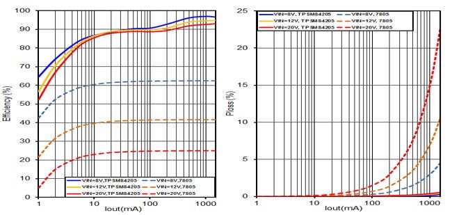 Figure 4 Efficiency and Power-loss
Comparison between the TPSM84205 and UA7805
Figure 4 Efficiency and Power-loss
Comparison between the TPSM84205 and UA7805The TPSM84203/05/12 has the same frequency spread-spectrum feature as the TPS54302 to reduce EMI caused by the switching regulator. With the proper external input filter, the TPSM84203/05/12 will easily pass the European standard (EN) 55022 Class B EMI test. Figure 5 is a graph of EN55022 Class B conducted emissions measurements for the TPSM84205.
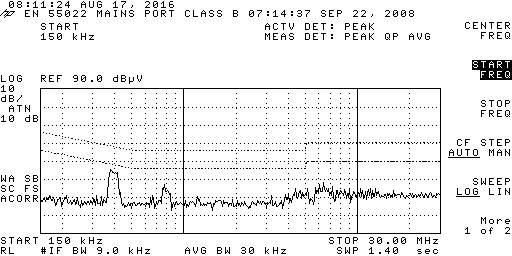 Figure 5 Conducted Emission
Measurements: vIN = 24V, vOUT = 5V and IOUT =
1.5A
Figure 5 Conducted Emission
Measurements: vIN = 24V, vOUT = 5V and IOUT =
1.5AThere are many benefits to gain from replacing a UA7805-type regulator with the TPSM84203/05/12 family – the overall efficiency will improve significantly by using a pin-compatible solution with the same BOM count, while the spread-spectrum design ensures that the solution helps meet EMI requirements.