SSZT842 december 2017 TPD2S300
Other Parts Discussed in Post: TPD2S300
In the last couple of years, more and more portal devices such as notebooks and smartphones have employed USB Type-C™ as the interface port. The USB Type-C connector is a totally new USB connector. It has a set of great profile, power rating and data transmission speed improvements. But the most important change about this charging protocol is that USB Type-C introduces a new pin, the configuration channel (CC) pin, to negotiate between different devices.
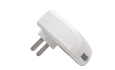
Legacy adapters use D+/D– lines to perform a handshake between two devices. The most common legacy adapters, as shown in Figure 1, usually have a Type A port as output so that different cables can be match with different phones; for example, an A-uB cable for Android phones, an A-lighting cable for iPhones, etc. USB Type-C also has an A-C cable so that it can be charged by legacy adapters.
 Figure 1 A Legacy USB Adapter
To give users the best usage experience, some USB Type-C product manufacturers have designed their USB Type-C products to support both the new USB Type-C charging protocols via CC as well as existing charging protocols. Employing D+/D- in current USB products, some of the charging protocols cannot be used for USB Type-C connectors (see Section 4.8 of the USB Type-C Cable and Connector Specification, Revision 1.2).
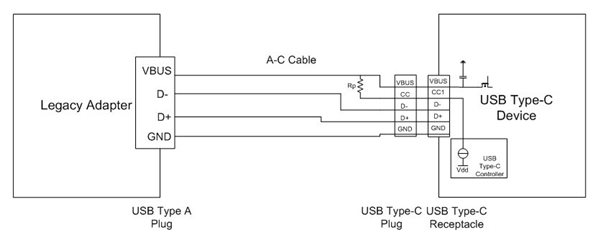
There lies the problem. A USB Type-C connector has an A-C cable to be compatible with legacy adapters and there is an internal pull-up resistor (Rp) inside the USB Type-C plug (see Section 3.5 of the USB Type-C specification) to enable the detection of a USB Type-C device. Once there is a DC voltage existing at VBUS and the USB Type-C plug is inserted to the USB Type-C device, VBUS will pull up the voltage level of the CC pin to notify the USB Type-C controller, as shown in Figure 2.
 Figure 2 Legacy Adapter to a USB Type-C Product Connection
Even the fast –charging protocols such as QC are not compatible in a USB Type-C connector, the irregular USB Type-C products, as mentioned above, are still going to support these high voltage protocols. In this case, the VBUS may increase to 9V or 12V after a successful handshake with a legacy adapter via D+/D- lines. This high voltage will be applied to the CC pin of the USB Type-C controller via Rp. Unfortunately, the most common USB Type-C controllers cannot handle such high voltage, because it is out of the USB Type-C specification. To prevent the USB Type-C controller from being damaged in the case of being tied to VBUS via Rp requires a compliant USB Type-C device.
One simple way to protect the USB Type-C controller is to add a Zener diode between the CC pin of the USB Type-C controller and ground. This Zener diode can clamp the CC line’s voltage within a safe range. But I need to highlight two things:
- The clamping voltage of the Zener diode should be higher than the normal voltage of the CC pin and lower than the maximum rating voltage. But because a Zener diode’s breakdown voltage always varies with its own current (in this case, proportional to the VBUS voltage) and temperature, selecting a proper Zener diode won’t be easy.
- The current flowing from VBUS to ground via the Zener diode brings additional losses. This current may be up to several milliamps in the worst case (given that VBUS may be up to 20V and Rp is lower than 10KOhm ).
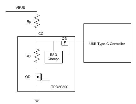
Another way to protect the USB Type-C controller is to use a blocking field-effect transistor (FET) , labeled as QB in Figure 3,QB to isolate the USB Type-C controller from VBUS. The QB is inserted between the USB Type-C receptacle and USB Type-C controller. It can be off when an overvoltage event occurs at the CC pin of the USB Type-C receptacle so that the USB Power Delivery controller does not see such a high voltage. However, this will bring an additional path consisting of a pull-down resistor (RD in Figure 3) and its control FET (QD in Figure 3). QD will be ON to perform the RD on CC pin in the event of a dead battery. The additional logic circuit for QD may also sacrifice some board space.
A good choice is to adopt a USB Type-C port protection integrated circuit (IC) such as the TPD2S300, which integrates all of the necessary functions for a USB Type-C device. This IC requires no additional protection and logic circuitry. Electrostatic discharge (ESD) protection is integrated as well. Figure 3 shows a typical circuit using the TPD2S300.
 Figure 3 TPD2S300 Circuit for the CC Pin
To protect the USB Type-C devices, such as power banks or smartphones, from irregular adapters or chargers on the market, additional protection for the USB Type-C port is necessary with Zener diodes, blocking FETs or protection ICs.