SSZT772 march 2018 AMIC110
Powering industrial Ethernet devices requires addressing specific aspects of industrial Ethernet and industrial applications.
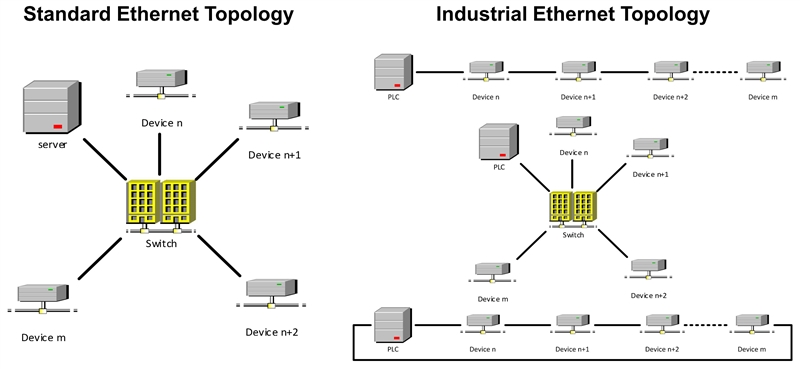
The biggest difference between standard Ethernet and industrial Ethernet is the topology, as shown in Figure 1. Standard Ethernet is a star topology, whereas industrial Ethernet includes a variety of line, tree and ring topologies.
 Figure 1 The Two Types of Ethernet
Topologies
Figure 1 The Two Types of Ethernet
TopologiesAside from the topology, factory automation devices operate at 24V, whereas telecom devices are powered at 48V. While those different versions have existed for a long time, the first power solution for Industrial Ethernet was just released: EtherCAT P. In this blog post, I’ll explain what EtherCAT P is before covering alternatives for 1000BASE-T and/or ring topologies or single twisted pair.
Introducing EtherCAT P: a Single Cable for Power and EtherCAT
 Figure 2 EtherCAT P Allows You to
Reduce the Number of Cables and Bring High-end Sensing to Movable Robot
Heads
Figure 2 EtherCAT P Allows You to
Reduce the Number of Cables and Bring High-end Sensing to Movable Robot
HeadsHowever, in the case of an industrial Ethernet with a line topology, the 25MHz of the Ethernet communication will be available at the output of the power supply and could therefore be coupled out on the transmit side. In that case, the transmitter would then suffer from noise from the receiver channel communication standard.
For this reason, EtherCAT P (which is an extension to EtherCAT) introduces a simple inductor-capacitor (LC) filter to ensure that the 25MHz from the 100BASE-T will be blocked before entering the power tree.
Another difference between PoE and EtherCAT P is that PoE offers only one 48V supply voltage, while EtherCAT P provides two independent 24V rails that are isolated from each other, shown in Table 1. In terms of power, PoE can deliver 71W (for 803.2bt Type 4), while EtherCAT P offers 24V x 3A ≥72W per voltage rail.
A major difference between the two technologies is that for PoE, you need two semiconductors for identification between the power-sourcing equipment (PSE) and the powered device (PD). The chip inside the PD is also responsible for setting the maximum power limit. But this brings two advantages: full power is only available if a valid connection is established, and PoE-capable devices can connect to non-PoE devices without damaging them.
In the case of EtherCAT P, you only need standard passives to couple power in – no additional semiconductors. This means the 24V supply is always present on the data line. However, the maximum power must be limited inside the PSE.
| POE | EtherCAT P | |
|---|---|---|
| Supply voltage | 48V | 2 x 24V (Us and Up, isolated form each other) |
| Power available at PD | Up to 71W for 803.3bt Type 4 | 2 x 72W (2 x 24V, 3A) |
| Identification before Power | Yes | No |
| Topologies | Point to point | Star, line, tree |
The EtherCAT P One Cable for Power and EtherCAT Reference Design shows an implementation of the power couple in-couple out circuitry of an EtherCAT P PSE. The reference design meets all requirements from the official “EtherCAT and EtherCAT P Slave Implementation Guide.” These requirements include features like reverse polarity protection, in-rush current limit and continuous current limit, all based on semiconductors from TI.
For EtherCAT communication, the reference design can connect to an EtherCAT-capable communication platform like the AMIC110 industrial communication engine (ICE) with an Ethernet cable. To showcase the power transfer functionality, you can connect two design boards with an EtherCAT P cable. You can also connect an EtherCAT master to the first reference design and an EtherCAT slave to the second reference design for a complete EtherCAT P demonstration system. For additional ease of evaluation, an optional 5V/12V buck module can be mounted onto the board as well.
Should your designs require compliance with Institute of Electrical and Electronics Engineers (IEEE) 802.3, check out the IEEE802.3bt New Features video, which will introduce you to the new IEEE 802.3bt PoE standard.