SSZT770 march 2018 UCC28780
Efficiency is the most crucial criteria for some power supplies. With high-efficiency controllers like the UCC28780, it is important now more than ever to understand how to conduct a proper efficiency measurement that adheres to regulation standards. In this post, I’ll show you how to properly connect and measure AC/DC power supply efficiency.
Proper Test Conditions:
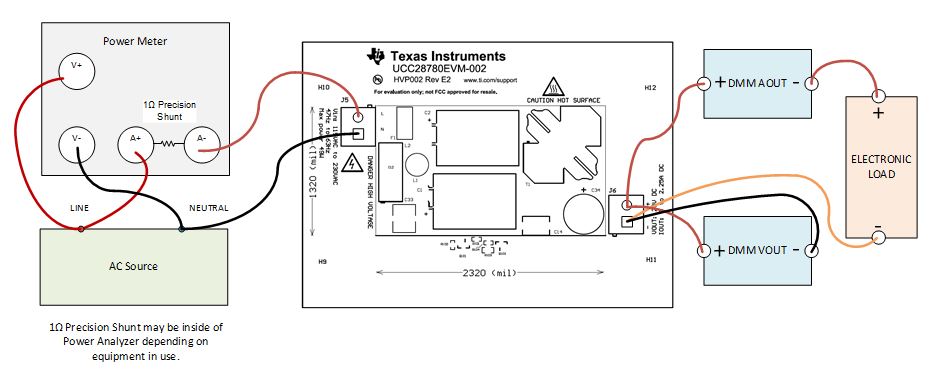
 Figure 1 UCC28780EVM Connection Diagram for Efficiency Measurements
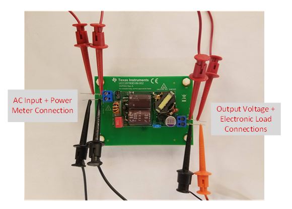
Now let’s move to the input side of efficiency measurements for AC/DC converters. A dedicated power meter is required, as the two-multimeter setup used on the output side would not be accurate for the input because the multi-meters would not account for the harmonic content like a power meter would. Similar to the output, your goal is still to place the measuring probes as close as possible to the board’s input. Both input and output connections are shown in Figure 2, and match the color scheme of Figure 1.
 Figure 2 Probe Connections for Efficiency Measurements
Proper Testing Procedure:
- Turn on an AC source with a high line voltage (230AC/50Hz for Europe or 115AC/60Hz for U.S.A) and with a 100% load. Let the device under test operate for at least 30 minutes to ensure that the board is warmed up and stable for
measurements.
- The unit under test is considered stable if the AC input power does not deviate/drift more than 5% from the maximum power value observed.
- If the AC input power is not
stable after five minutes, continue to monitor the input power in five-minute periods until the reading is stable.
- If after many waiting periods the input power is not stable, follow the International Electrotechnical Commission (IEC) 62301 standard test procedure, which states to measure the average power, or derive the power from an average energy measurement.
- After the initial warm up period, take the first measurement at a 100% load. Use an AC power meter to monitor the input power for a period of five minutes before assessing the stability of the power supply.
- The remaining load conditions are 75%, 50%, 25%, 10% and 0% load, in that order. You only need one warm up time of 30 minutes, so these subsequent measurements only need a minimum of five minutes to become stable enough to record measurements.
A test procedure would then look like this:
- Warm up the unit under test for 30 minutes under a full load, 230VAC/50Hz or 115VAC/60Hz.
- Assess the stability of the unit and take measurements if stable.
- If not stable, continue to monitor output until stable.
- Drop load to 75%; monitor for five minutes to assess stability then take measurement.
- Drop load to 50%; monitor for five minutes to assess stability then take measurement.
- Drop load to 25%; monitor for five minutes to assess stability then take measurement.
- Drop load to 10%; monitor for five minutes to assess stability then take measurement.
- Drop load to 0%; monitor for five minutes to assess stability then take measurement.
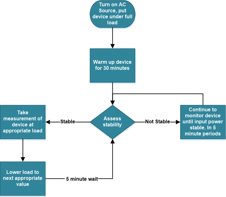
Figure 3 outlines the test procedure in a flowchart diagram.
 Figure 3 Efficiency Measurement Procedure