SSZT765 march 2018 HD3SS3212 , HD3SS3220 , TUSB212 , TUSB213 , TUSB542 , TUSB544 , TUSB564
USB Type-C™ enables the transfer of data, video and power over a single cable and connector. The flip-ability of the USB Type-C connector introduces connection pin redundancy, which requires a signal switch in order to bring the correct data path to the central processing unit (CPU) for signal processing.
There are two types of signal switches: USB only and USB plus video. Figure 1 shows USB-only switches applied in a USB Type-C end-to-end system.
 Figure 1 USB Type-C End-to-end USB
Solution
Figure 1 USB Type-C End-to-end USB
SolutionThe main purpose of a USB signal switch is to select the right USB 3.0 transmit (SSTX) and receive (SSRX) pins based on connector orientation from the configuration channel (CC) controller and route the active pins to the CPU. There are two types of signal switches or multiplexers: passive or active switches. The HD3SS3212 is a passive switch that can support a 10Gbps USB speed. The HD3SS3220 is 10Gbps passive switch with an integrated CC controller. If signal integrity is a concern in your design, you can use an active redriver switch to improve signal quality and help pass USB compliance. The TUSB542 is a USB 5Gbps redriver switch and the TUSB1042 is a USB 10Gbps redriver switch.
Among the many convenient features of USB Type-C, one cool advantage is the clever design of its physical layer, which enables DisplayPort™ (DP) protocol and signal pass through over its connector and cable. This brings tremendous benefits, not only because it results in a small-footprint connector and a lightweight cable, but because it enables simultaneous video and data transfer as well as power charging of the device, all through a single connection.
Video Electronics Standards Association (VESA)-specified DisplayPort Alternate Mode on USB Type-C allows four high-speed DisplayPort lane transfer over the USB Type-C high-speed data path, and auxiliary (AUX) channel signaling transfer through sideband-use (SBU) channels. The USB Type-C physical layer can deliver the DisplayPort 1.4 standard up to 8.1Gbps per lane, which is enough to support 4K or 8K video over the USB Type-C interface.
Enabling video over USB Type-C requires a signal multiplexer in the video source and a signal demultiplexer in the video sink to multiplex and demultiplex the video and USB signal. Figure 2 shows the signal multiplexer choices and placement in an end-to-end USB Type-C Alternate Mode system.
 Figure 2 USB Type-C Alternate Mode
End-to-end Solution
Figure 2 USB Type-C Alternate Mode
End-to-end SolutionThe HS3SS460 is a passive Alternate Mode multiplexer that you can use in both the source and sink sides, supporting USB 3.0 and DisplayPort 1.2 at 5.4Gbps.
The TUSB546 and TUSB1046 are Alternate Mode redriver switches for the source side. Both are pin-to-pin compatible and support DisplayPort 1.4 at 8.1Gbps. The only difference is that the TUSB546 supports USB 3.0 at 5Gbps, while the TUSB1046 supports USB 3.1 Gen 2 at 10Gbps. In addition to supporting DisplayPort over USB Type-C Alternate Mode, these devices also support High-Definition Multimedia Interface (HDMI) over USB Type-C Alternate Mode.
The TUSB544 is a bidirectional USB Type-C redriver also supporting Alternate Mode that you can use when the signal multiplexer is integrated into the CPU and you need a redriver to improve signal integrity to pass compliance.
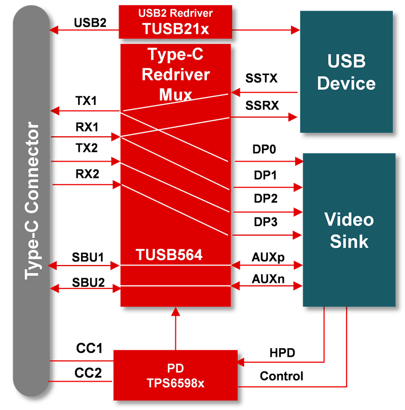
The TUSB564 is a USB Type-C Alternate Mode redriver multiplexer for the sink side, which makes it a good fit for docking, monitoring and virtual reality applications. The device supports USB 3.0 and DisplayPort 1.4 at 8.1Gbps signal demultiplexing while improving signal quality by compensating for printed circuit board (PCB) trace or cable loss, helping your system pass USB and DisplayPort compliance. Figure 3 shows the TUSB564 signal path in a typical use case.
 Figure 3 TUSB564 Functional
Diagram
Figure 3 TUSB564 Functional
DiagramIn a USB Type-C system, USB 2.0 has its own data path. Typically, the USB 2.0 D+ and D- redundancy pins are connected, so you won’t need a signal switch. However, it is always wise to add a USB 2.0 redriver such as the TUSB212 or TUSB213 in a USB Type-C system to enable better USB 2.0 signal quality.
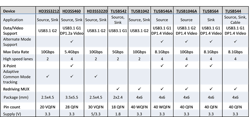
Figure 4 summarizes USB Type-C signal switch key feature differences to help you find the most relevant solutions for your next USB Type-C project.
 Figure 4 USB Type-C Signal Switch
Comparison