SSZT738 april 2018 SN65LVDS93B , SN65LVDS93B-Q1
A human-machine interface (HMI) usually includes a textual or graphical view of automated system conditions and operations. HMIs are widely used in factory automation, motion control systems, industrial robots for smarter automation, and computer numerical control (CNC) systems with highly interactive interfaces and touch-screen support. Industrial HMIs need to function within a factory setting, which requires fieldbus connectivity and low-power, fanless operation.
Thin-film transistor (TFT) liquid crystal display (LCD) modules have a variety of input interfaces such as low-voltage differential signaling (LVDS) and red-green-blue (RGB)666 or RGB888. Depending on the display interface, an HMI will require only a serializer or both a serializer and deserializer.
TFT LCD modules with an LVDS input interface only need a serializer, because the outputs of the serializer are LVDS and can directly connect to the input of the TFT LCD module. However, TFT LCD modules with an RGB input interface need both a serializer and deserializer. The deserializer converts serial LVDS data to a parallel interface in RGB format that directly connects to the TFT LCD module.
Figure 1 depicts a functional breakdown of an HMI programmable logic controller (PLC) panel. The main processor receives the video data from external memory and a wired interface, performs the digital processing, and then passes parallel RGB video data to a serializer. The serializer converts the parallel data to serial LVDS pairs and outputs the LVDS video to the TFT LCD panel.
 Figure 1 HMI PLC Panel Block Diagram
The processor graphics unit video interface output is 18/24 bits of parallel RGB data. If there is a long cable distance between the main processor and the LCD panel (from 10m to 40m), you will need to use a high-speed serializer to serialize the parallel output data from the main processor to LVDS before it goes to the LCD video input.
When compared to other communication methods, a serializer/deserializer (SerDes) provides these advantages:
- A robust link, with integrated emphasis/equalizer (EQ).
- Embedded clock, data, and termination for better signal integrity (less skew, jitter, crosstalk).
- High electromagnetic interference (EMI) resistance through differential signaling, data encoding, Spread-Spectrum Clocking SSC, and fewer parallel cables and connectors.
- The ability to use lower-cost cables.
- Takes up less space and makes for easy printed circuit board (PCB) layout.
How do you select a SerDes that will work well with your TFT LCD display? Some key parameters in the TFT LCD data sheet are the most imperative. The SerDes needs to meet these parameters in order to ensure that the TFT LCD display and the HMI system work properly:
- Number of parallel RGB inputs required:
18-bit devices are designed for 6-bit RGB video for a total of 18 bits. 21-bit devices are designed for 7-bit RGB video for a total of 21 bits. 24-bit devices are designed for 8-bit RGB video for a total of 24 bits. In addition, there are four extra control bits (HSYNC, VSYNC, DE, and an optional general purpose bit). For example, the SN65LVDS93B is for 24-bit RGB interfaces, but is labeled as a 28-bit device because of the four extra control bits.
- Number of serial LVDS outputs or parallel RGB outputs required: There may be three or four serial LVDS input pairs on a TFT LCD module with an LVDS interface. On a TFT LCD module with a parallel RGB interface, a deserializer is needed to convert the LVDS signals back to parallel RGB signals.
- Data strobe edge. Does the display require a rising edge data strobe or a falling edge data strobe? Both the SN65LVDS93B and SN65LVDS93B-Q1 offer data strobing at rising and falling edges and are compatible with most deserializers and LCD panels.
- Operating temperature range. SerDes devices operate in one of these temperature ranges: 0°C to 70°C, -40°C to 85°C, -40°C to 105°C or -40°C to 125°C
- Maximum and minimum pixel clock frequency:
The pixel clock is the product of active horizontal pixels, active vertical pixels, percent blanking, and refresh rate. For example, if there are 1280 total horizontal pixels, 720 total vertical pixels, the refresh rate is 60Hz, and percent blanking is 29.15%, the pixel clock frequency is 1280 x 720 x 60 x (1 + 29.15%) = 72MHz. Both the serializer and deserializer need to meet 72MHz in the pixel clock frequency range.
Equation 1 is the pixel clock formula:
Pixel Clock = H-pixels x V-pixels x FPS x (1 + Percent Blanking) (1)
Frames per second (FPS) is the refresh rate and varies from 24Hz to 70Hz (60Hz is common) and the blanking varies from 3% to 39%.
- Line rate: The data line rate (or throughput) is the effective payload of video data, and is derived from the required pixel clock frequency and the number of parallel RGB inputs required, as shown below in equation 2.
Line Rate = Pixel Clock x Number of parallel RGB inputs required (2)
For example, if the required pixel clock frequency is 72MHz and the number of parallel RGB inputs required is 24-bits, then the SerDes must be able to support a throughput of 1.728Gbps.
- Pixel clock and line rate requirements for common resolutions:
Assuming a refresh rate of 60Hz, the table below illustrates pixel clock and line rate requirements for common resolutions using equations (1) and (2):
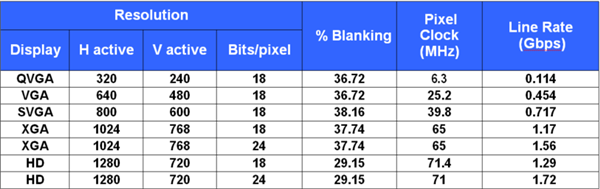
|
The SN65LVDS93B and SN65LVDS93B-Q1, for example, are SerDes that can support all of the above resolutions. Looking at the datasheet, the pixel clock range for these devices is 10MHz – 85MHz, and they support a line rate of up to 2.38Gbps for 28-bits of data. This is equivalent to 8-bit RGB (24-bits of video data) except there are four extra control signal bits (HSYNC, VSYNC, DE, and an optional general purpose bit) that are included in the total supported throughput calculation for the SerDes.
If the SerDes don’t meet these parameters, data on the TFT LCD display may display incorrectly, or not at all, and cause the HMI system to function unexpectedly.
Leave a comment below if you would like to learn more about anything discussed here, or if there is an LVDS topic you would like to see in the future.