SSZT709 may 2018 SN65HVD888 , THVD1505
The RS-485 interface is popular because of its robustness; the use of differential signaling effectively rejects common-mode noise on the bus. To make the communication work, the transceiver and receiver have to match the pins: A to A and B to B. In some RS-485 applications, however, the bus polarity information might not be available on the receiver ends or the polarity could be mistaken.
Auto-polarity RS-485 transceivers like the SN65HVD888 and THVD1505 can detect the bus polarity automatically so that the two bus wires can be connected during installation either way. For example, the A pin of the device can be connected to any one of the two bus wires and B pin can be connected to the other wire. Using this configuration reduces costs and helps increase system reliability. The bus polarity feature could be beneficial for systems with high installation rates, such as IP cameras, E-meter, air conditioning and lighting. In the event that the RS-485 connection is installed backwards, the device can self correct the polarity instead of requiring an installation team to revisit the site and correct the error.
The mechanism of auto-polarity detection relies on generating enough voltage difference on the idle bus in the system using bias resistors, RFS and RT2, shown in Figure 1.
 Figure 1 Auto-polarity RS-485 Bus
Network
Figure 1 Auto-polarity RS-485 Bus
NetworkBecause designing this bias (fail-safe) network is sometimes not as straightforward as it looks, in this post I’ll apply two equations to make the calculations. After the resistor values are fixed, I will show the network’s impact on the loading condition of the system.
To design a proper fail-safe network, you need to meet two fundamental conditions. First, the equivalent resistance of the network, RFS and RT2, needs to be equal to the characteristic impedance of the cabling. In this setup, this value is presented by the termination resistor value of the bus, RT1. Secondly, the voltage generated on the idle bus should be bigger than the input threshold voltage, Vit, of the receiver. Provided with the first condition, the voltage drop on RT2 from the network itself should be twice the voltage required. In other words, the calculation is only based on the resistors in the dotted blue box of Figure 1, excluding RT1.
From the first condition, you can redraw the network by connecting the virtual ground, Vcc and GND, of RFS together (Figure 2).
 Figure 2 Equivalent Circuit of a
Fail-safe Network
Figure 2 Equivalent Circuit of a
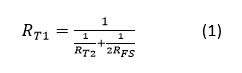
Fail-safe NetworkBy doing this, you can easily calculate the equivalent resistance using Equation 1:
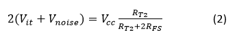
From the second condition, suppose that the minimum Vcc is 4.5 V and Vit is 100 mV. You can also include 50 mV of noise margin on top of Vit (Equation 2):
Now that you have two equations with two variables, you can put them together using Equation 3:
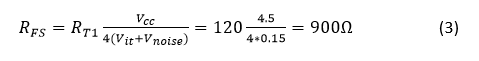
From here, it’s easy to deduce the value of RT2. In this example, it is 128 Ω.
After you have obtained all resistor values, you can evaluate their impact on the system. In the RS-485 standard, 375 Ω represents the maximum loading of the bus (RINEQ in Figure 3), or (1/375) S in conductance. Assume the bus voltage is 1 V. This means that the most leakage current the bus can take is about 2.67 mA single-ended.
RS-485 specifies a term of unit load (UL) to represent a load impedance of approximately 12 kΩ. If each node has a 96 kΩ input resistance (1/8 UL), it would take 256 nodes to generate equivalent leakage. 900 Ω RFS takes 1.11 mA away from the total current budget (the blue arrow in Figure 3). Therefore, the nodes on the bus can have a maximum leakage of 1.56 mA (the red arrow in Figure 3). 1.56 mA divided by 104 µA (1 V/96k Ω) is equal to 149 nodes.
 Figure 3 Auto-polarity RS-485 Bus
Network Showing Loading Conditions
Figure 3 Auto-polarity RS-485 Bus
Network Showing Loading ConditionsA proper fail-safe network for SN65HVD888 shows that the bus can support up to 149 1/8UL nodes with the network.
Additional Resources
- Read the Analog Design Journal article, “RS-485: Passive failsafe for an idle bus.”