SSZT682 june 2018 LM3880 , LM3881 , TLV62568 , TLV62569 , TLV803
Next-generation smart appliances are getting smarter, thanks to breakthroughs in wireless connectivity and human machine interface. Processors with highly integrated graphic accelerators, like Sitara™ AM335x processors can help you realize better touch interfaces, bigger screens with higher resolution and high-definition cameras. Processors with an Arm® or digital signal processor (DSP) core with up to 1GHz speeds can help you integrate multiple sensors, voice recognition and home automation. And processors with wireless connectivity can help you achieve an interactive connection between appliances or the cloud through the Internet of Things (IoT).
Typically, processors or digital devices require different power-supply voltages, mixed together on the board with the correct power sequence. Power-supply voltages turned on or off with an incorrect power sequence can cause reliability problems such as characteristics degradation, inrush currents and latchup conditions. Powering processors in the correct power up/down sequence is a challenge, requiring the design of a power-tree architecture that trades off between efficiency, cost and size.
Another design challenge in managing power off sequencing is uncontrolled power off, which means there is no sign when power off occurs. Before the supply power drops down to ground, there should be enough reaction time for the power tree to manage the power rails drop down with correct sequence, otherwise incorrect power sequencing will occur and that may cause reliability problems.
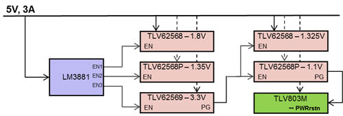
A power-management integrated circuit (PMIC) is capable of meeting a strict power sequence. DC/DC converters with the necessary sequencing circuits are another flexible option. The latter solution enables high flexibility for board layout, high efficiency under low-power mode and a cost-optimized bill of materials (BOM) with a small board size. Figure 1 shows an efficient power-tree solution using DC/DC converters with sequencing circuits.
 Figure 1 Five-rail Power Sequencing
Platform Diagram
Figure 1 Five-rail Power Sequencing
Platform DiagramThe 5V input voltage rail is configured as the DC bus for each device. In Figure 1, the five voltage rails on the TI TLV62568 device provide high efficiency and the power up/down sequence is divided into five orders. The LM3881 provides three orders by providing three open-drain output flags as signals for DC/DC converters, the power good pin provides one order and the TLV803 provides one order. The TLV803 is a supervisor monitoring input voltage rail, which means it can detect the moment when uncontrolled power off occurs.
Because uncontrolled power off is a situation when the power supply is removed unexpectedly, such as when someone yanks a cord out of an outlet without powering down the device first, the processor is not involved in the process. In this situation, the reaction time allowed for the power-supply rails’ power-off depends on the input capacitor’s discharge time. In controlled power off, power off is controlled by the processor, achieved by connecting the processor’s power-management I/O to the power sequencing controller’s enable pin. Figure 2 shows power off situation examples in daily life.
 Figure 2 Uncontrolled Power off vs.
Controlled Power off
Figure 2 Uncontrolled Power off vs.
Controlled Power offIn an uncontrolled power-off situation, the discharge time is short and may cause the power-down sequence to be out of order. The most efficient approach of controlling uncontrolled power off is to use a supervisor to monitor the input voltage and generate a sudden flag, indicating that power off occurred. In the 12mm x 12mm, 5-Rail Power Sequencing for Application Processors Reference Design, the supervisor monitors the input voltage rail. When the input voltage rail ramps down, the output of supervisor goes low, which disables the main oscillator inside the processor, reduces the load current and increases the discharge time.
Figure 3 shows the test result of the power tree shown in Figure 1 under an uncontrolled power off, which is achieved by directly removing the DC power supply and setting the input capacitor to 220µF.
 Figure 3 Power Sequencing Test
Result
Figure 3 Power Sequencing Test
ResultFigure 3 demonstrates one of the test results from different rails powering up in the correct order and powering down in the correct and reverse order. To see the other test results, please visit the 12mm x 12mm, 5-Rail Power Sequencing for Application Processors Reference Design mentioned above. The TLV803 monitors the input voltage. When detecting the input voltage’s power off, the TLV803’s output will arrive at a low level immediately to close the main clock in the processor in order to reduce power load and enable enough time for the other power rails to power off.
Additional resourcesCheck Out These Other TI E2E Community Blog Posts:
- Check out these other TI E2E Community blog posts:
- Find the best solutions for your next-generation appliance designs.