SSZT675 june 2018 TLC5971
LED signage and lighting applications such as industrial stack lights you might know from industrial machinery or big LED displays that are used in stadiums have a common problem of limited possibilities for power dissipation. It’s important in industrial environments that these lights and signage are able to dissipate the heat that is generated, to maximize the lifetime of the LEDs. When applications are using linear LED drivers it is required that you minimize the voltage drop in the linear LED driver, which in turn requires regulation of the voltage of the supplying regulator based on the LED forward voltage. This technique is called dynamic headroom control.
As long as you always have the same current, the voltage drop of the LEDs will remain constant over temperature and process variations. For example, you could calculate the feedback network of an adjustable regulator to have a residue voltage of 0.5V, which is just a bit above the minimal value. It is necessary to have enough of a voltage drop so the linear regulator can work, even over temperature variation and component tolerances, but it also has to be low voltage to minimize the power dissipation.
In all cases, you should consider the variation of the forward voltage mentioned in the data sheet. For a green LED, this could be between 2.7V and 3.4V at 10mA, so you should set your voltage regulator to at least 3.4V + 0.5V = 3.9V. It is better not to go too close to the minimum value, as you always have tolerances in the reference of the voltage regulator and the resistors.
For one LED the power dissipation will be about 12mW, which is in most cases nothing to worry about. But many applications don’t have just one LED, and you might want to increase the current.
Let’s look at the TLC5971 red-green-blue (RGB) LED driver with one voltage regulator. The blue LED has the highest forward voltage: 3.8V. Thus, you have to design the voltage regulator for 4.3V, maybe with some more headroom for higher current. The device has four RGB channels, so the power dissipation will be up to 4 × ((4.2 – 3) + (4.2 – 2.7) + (4.2 – 2.1)) × 0.01 = 192mW. If you go as high as 20mA and use only one regulator for all colors of 5V (which is available as fixed output voltage) the power dissipation is even higher.
How Can the Power Dissipation Be Reduced?
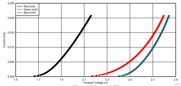
One way to reduce power dissipation is to use one regulator for each color, or at least one voltage for the red string and another voltage the green and blue strings. The voltage of green and blue is close to another, but the voltage of the red LED string is lower than green and blue.
 Figure 1 LED forward voltage of
different colored LEDs
Figure 1 LED forward voltage of
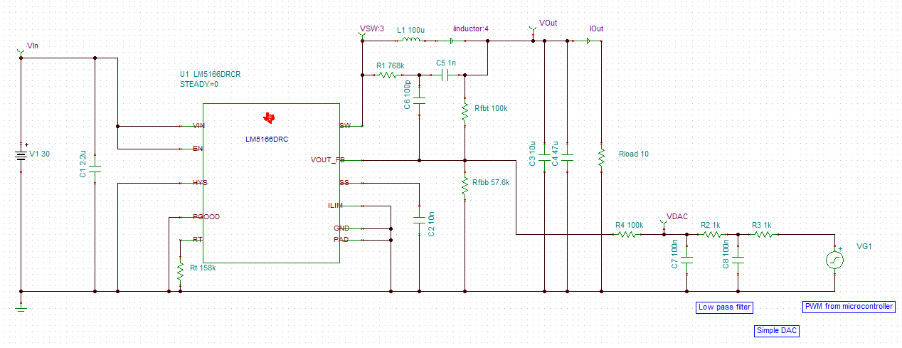
different colored LEDsIt's also possible to achieve a further reduction by adjusting the voltage of each regulator; one easy way is to inject a voltage in the feedback network of a regulator. You could use a digital-to-analog converter (DAC) or build your own DAC by using a pulse-width modulation (PWM) and a low-pass filter. Figure 1 shows a simulation for a controlled voltage regulator. On the right is a PWM signal coming from a microcontroller (MCU), low pass-filtered and injected into the feedback network.
 Figure 2 Simulation of a PWM for
controlling a voltage regulator
Figure 2 Simulation of a PWM for
controlling a voltage regulatorAs in most systems where a MCU is present, the MCU can measure the voltage drop of the LED driver and set the PWM for voltage regulator control. This control loop does not have to be fast or very precise, since it does not have a visible effect other than higher power dissipation. You can simulate the whole power supply, including the PWM from the MCU. In the simulation shown in Figure 1, the PWM is generated by a voltage generator configured to generate a 20kHz PWM, with an increasing duty cycle from 0 to 100% within 1s.
The simulation does takes a long time, so you might want to simulate the DAC after changing parameters to verify that it is working. By simulating the two main parts separately, it will speed up the entire simulation. A PWM duty cycle sweep should look like Figure 2.
 Figure 3 Resulting DAC voltage on
varying PWM duty cycle
Figure 3 Resulting DAC voltage on
varying PWM duty cycleInjecting a positive voltage into the feedback network will reduce the output voltage depending on the voltage and the resistors. When injecting 0V, the output voltage is at its maximum. Figure 3 shows the effect of the injection on the output voltage.
 Figure 4 Simulation results
Effect of DHC on Total Power Consumption
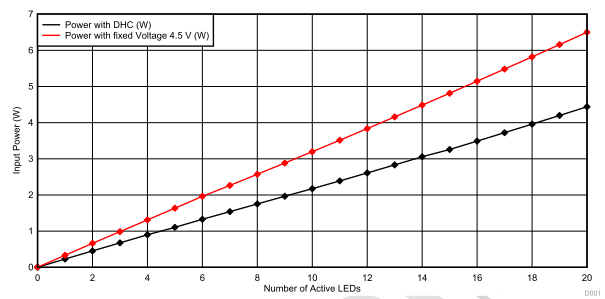
TI implemented dynamic headroom control by injecting voltage in the feedback network in the RGB Signal Light with IO-Link Interface Reference Design for a stack light with 20 RGB LEDs and five TLC5971 LED drivers. As shown in Figure 4, you end up at 6.5W of total system power consumption, with a fixed 4.5V for the LED driver and 20mA current per LED. Enabling the regulation of the voltage to a voltage drop of 0.5V at the LED driver decreases the total power dissipation to 4.5W.
 Figure 5 Power dissipation comparison
with and without dynamic headroom control
Figure 5 Power dissipation comparison
with and without dynamic headroom controlThe dynamic headroom control technique can help reduce the high power dissipation of LED signage and lighting applications using LED drivers. The technique enables significant power reductions by giving you the ability to regulate your voltage regulator.
Additional Resources:
- Learn how to light up your design with TI’s LED driver integrated circuits.