SSZT660 July 2018 MSP430FR2355
Imagine a world where you can easily configure your analog options on the fly without any need to change onboard components.
The Smart Analog Combo module integrated within the MSP430FR2355 MCU that allows you to do just that. The MSP430R2355 MCU contains four of these modules, giving you the tools and flexibility to realize your design.
What Is a Smart Analog Combo?
As you can see in Figure 1, the Smart Analog Combo module is an integrated configurable analog block that is configurable as an operational amplifier (op amp), programmable gain amplifier (PGA) or 12-bit digital-to-analog converter (DAC) without having to change any external hardware components.
 Figure 1 Smart analog combo module diagram
The module’s easy configurability enables you to save time; its integration within the MSP430™ MCU opens up board space; and the fact that you can configure the module through software allows for maximum future-proofing flexibility.
The Smart Analog Combo, combined with the 105°C maximum operating temperature rating of the MSP430FR2355, enables this MCU to provide a robust option for projects such as smoke detectors/fire safety devices, battery packs and much more.
The MSP-EXP430FR2355 LaunchPad™ Development Kit
The MSP-EXP430FR2355 LaunchPad development kit in Figure 2 is the evaluation tool for the MSP430FR2355.
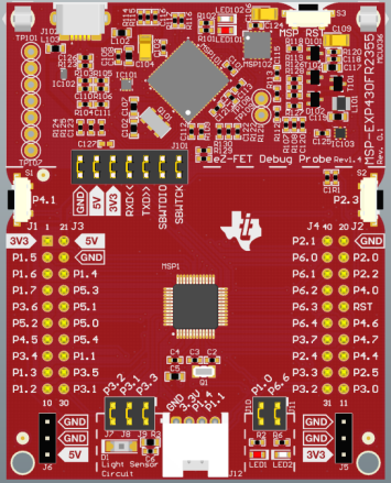 Figure 2 MSP-EXP430FR2355 LaunchPad development kit
The Smart Analog Combo graphical user interface (GUI), as seen in Figure 3, is a demo for the MSP-EXP430FR2355 LaunchPad development kit enables you to evaluate the power of the integrated configurable analog on the MSP430FR2355 MCU with an interface full of sliders, drop-down selections and visual representations. In the demo, you can generate a function using the DAC, measure your own signal using the pins of the LaunchPad™ development kit, or measure the output with the on-chip 12-bit analog-to-digital converter (ADC).
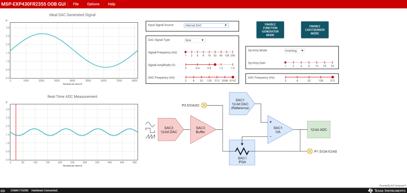 Figure 3 Smart Analog Combo GUI
How to Get Started with the Smart Analog Combo GUI
Plug in your MSP-EXP430FR2355 LaunchPad development kit using the included Micro-USB cable. Go to dev.ti.com on your web browser. Your device should be auto-detected, as noted on the left. Select Run Interactive Demos from the GUI Composer Gallery, or go to dev.ti.com/gallery and search for “MSP-EXP430FR2355,” as shown in Figure 4. Select the out-of-the-box demo from the options.
 Figure 4 Dev.ti.com Gallery
Once you’re in the Smart Analog Combo GUI, make sure to select Enable Function Generator Mode in the upper-right part of the screen. You are now set up to start using the demo.
What You Can Do with the Smart Analog Combo GUI
Using the Input Signal Source drop-down menu (Figure 5), you can select between the following options:
- Internal DAC: Generate a signal from the 12-bit DAC, send to the PGA, and read using the 12-bit ADC.
- P1.6 OA1 – Inverting PGA IN: Hook up a signal to pin 1.6 on the LaunchPad development kit and feed to the inverting PGA.
- P1.7 OA1+ Non-Inverting PGA IN: Hook up a signal to pin 1.7 on the LaunchPad development kit and feed to the noninverting PGA.
- P1.5 ADC Direct IN: Hook up a signal to pin 1.5 on the LaunchPad development kit directly to the 12-bit ADC.
 Figure 5 Input Signal Source Drop-down Menu
Generating a Signal Using the Internal 12-Bit DAC
Let’s try out the internal DAC drop-down option – there are two boxes. The top-left graph contains the signal generated by the DAC and the bottom-left graph is what the ADC measures. See Figure 6 below. By default, you should see the generation of a sine signal.
The block diagram below shows two smart analog combos in this configuration: one as the internal DAC and one as a PGA. Figure 6 also shows where the top-left graph is generating the signal and the bottom-left graph is measuring the signal.
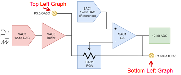 Figure 6 Smart Analog Combo Modules Block Diagram
Let’s modify the waveform. In the DAC signal type box, select the SAWTOOTH waveform from the drop-down menu. Increase the signal frequency to 8Hz; you should now see the waveform shown in Figure 7 on the left side.
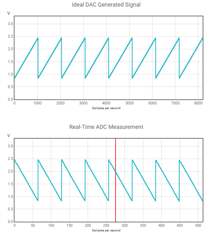 Figure 7 Sawtooth Inverting Waveform with a Signal Frequency = 8Hz
There are also options such as DAC frequency and signal amplitude. If you decrease the DAC frequency, you’ll notice the change in your waveform’s resolution. You can also change the signal amplitude through the DAC itself, or add an op-amp gain in the op-amp section.
If you switch the signal to noninverting and add a gain of 2, you will notice that the signal is now flipped and increased in amplitude, as shown in Figure 8.
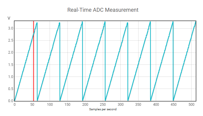 Figure 8 Sawtooth Noninverting Waveform with Signal Frequency = 8Hz, Op-amp Gain = 2
You have now successfully run through all of the different options when generating an internal DAC signal on the Smart Analog Combo GUI. You can see that this GUI is a powerful tool with which you can evaluate the configurable analog on the MSP430FR2355. Grab an MSP430FR2355 LaunchPad development kit today. Learn more about the MSP430FR2355 MCU LaunchPad development kit.