SSZT656 july 2018 ISO1410 , ISOW7841 , SN6501
- 1
-
2
- 3
- 1. When Is Isolating an RS-485 Bus Necessary?
- 2. How Many Nodes Can You Connect to an RS-485 Bus?
- 3. What Is the Speed vs. Length Correlation for Isolated RS-485?
- 4. What Is Fail-safe Biasing, and How Do You Design for It?
- 5. When Do You Need Termination on an RS-485 Bus, and What Are the Advantages and Drawbacks to the System?
- 6. What Kind of Transient Protection Do You Need with Isolated RS-485 Devices?
- 7. How Do You Generate Isolated Power for an Isolated RS-485 Node?
- What Questions Did We Miss?
- Additional Resources
By Anthony Viviano and Vikas Thawani
Looking for more information about RS-485? We’re here to help. Based on TI E2E™ Community feedback, we compiled a list of the most frequently asked questions about isolated RS-485 transceiver design challenges. We hope this list will provide useful insights when isolating signal and power for RS-485.
1. When Is Isolating an RS-485 Bus Necessary?
Isolation prevents direct current (DC) and unwanted alternating current (AC) between two parts of a system, while still enabling signal and power transfer between those two parts. Isolation typically protects electrical components or humans from dangerous voltage and current surges; isolation for human safety is called reinforced isolation. Isolation prevents ground loops which are common between nodes communicating at long distances. Isolation also allows communication between nodes with ground potential difference much higher than what the RS-485 standard recommends.
2. How Many Nodes Can You Connect to an RS-485 Bus?
To estimate the maximum number of bus loads possible, RS-485 specifies a hypothetical term of a unit load (UL), which represents a load impedance of approximately 12kΩ. The Telecommunications Industry Association/Electronic Industries Alliance (TIA/EIA) RS-485 standard mandates a maximum of 32 ULs that can be added to an RS-485 bus. The UL of a node is calculated by the worst-case ratio of the input voltage divided by the leakage current, as shown in equation 1:
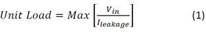
Once you’ve established the UL of the node, equation 2 calculates the maximum number of nodes:
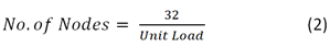
Most of TI’s isolated RS-485 transceivers have a UL of 1/8, translating to a maximum of 256 nodes on an RS-485 bus.
For more information about UL and the number of nodes that can connect to an RS-485 bus, see the Analog Applications Journal article, “The RS-485 unit load and maximum number of bus connections.”
3. What Is the Speed vs. Length Correlation for Isolated RS-485?
There is an inverse relationship between signal rate (speed) and cable length. The exact relationship depends on the resistance and inductance of the cable itself. When building an RS-485 network, the choice of cable can be as important as the transceiver, in order to ensure reliable communication over the necessary distance. Figure 1 is a graphical representation of the signal rate to cable length correlation. Region 3 of the figure shows the maximum cable length regardless of signal rate; in this area of the curve, the DC resistance of the cable causes attenuation in the signal and limits the maximum communication distance. Region 2 illustrates the inverse relationship between signal rate and cable length caused by transmission line losses, which will increase with a longer cable. In Region 1, you can neglect transmission line losses; the driver’s rise and fall times determine the main limitation on the maximum data rate. The RS-485 standard recommends a maximum signal rate of 10Mbps; however, with today’s technology, signal rates as high as 50Mbps are available.
 Figure 1 Signal Rate and Cable Length
Relationship
Figure 1 Signal Rate and Cable Length
Relationship4. What Is Fail-safe Biasing, and How Do You Design for It?
In order to comply with RS-485 standards, the receiver output must generate a logic level high when the differential input (VID) is more than 200mV, and must output a logic level low when VID is less than -200mV. However, you can generate an invalid output under three scenarios:
- Open bus conditions, such as a broken cable or a disconnected connector.
- Shorted bus conditions, such as a cable insulation breakdown shorting the twisted pair.
- Idle bus conditions that occur when no driver on the bus is actively driving.
In any of these scenarios, for a terminated transmission line, the RS-485 receiver VID would be zero and a non-fail-safe receiver output would be indeterminate.
Fail-safe biasing provides a differential voltage to the idle bus in order to maintain the receiver at a logic high level. If you don’t take fail-safe biasing into account, the termination resistors can lower the bus voltage to 0V, leading to an incorrect output or signal oscillation. You can design fail-safe biasing by using a resistor network along with an RS-485 transceiver. TI’s isolated RS-485 transceivers all have integrated fail-safe basing for open, short or idle bus situations, eliminating the need for external circuitry to achieve this functionality.
5. When Do You Need Termination on an RS-485 Bus, and What Are the Advantages and Drawbacks to the System?
In most RS-485 applications, termination resistors match the characteristic impedance of the cable to prevent signal reflections. Termination resistors should be placed at each end of an RS-485 cable. There are some short-distance-communication cases where the network will operate normally without termination resistors, but terminating the line is a best practice for all applications. The drawback of termination resistors is the DC loss generated by the resistance, which leads to increased power losses in the system. Even with this drawback, however, termination resistors are still a good idea for the majority of applications.
6. What Kind of Transient Protection Do You Need with Isolated RS-485 Devices?
Transient protection on an isolated RS-485 device depends on the type of disturbance - such as electrostatic discharge (ESD), electrical fast transient (EFT), or surge - expected in the end system and the level of protection needed. TI’s portfolio of isolated RS-485 transceivers will have some level of internal transient protection on the integrated transceiver bus terminals with respect to floating isolated ground. In addition to this, with proper system design, you can use the isolation barrier to present high impedance to these transients. If you aren’t expecting differential transients in your system and test all transients with respect to end-equipment earth, then connecting protective earth (PE) to the logic side of isolated transceiver will create a scenario where all high-voltage transients occur across the isolation barrier. Connecting PE to logic side can potentially eliminate external components such as transient voltage suppression (TVS) diodes or pulse-proof resistors.
Figure 2 illustrates these techniques for enhanced transient protection using the ISO1410.
 Figure 2 Half-duplex-isolated RS-485 Transceiver with Optional Bus-protection Components
7. How Do You Generate Isolated Power for an Isolated RS-485 Node?
There are several options to generate isolated power for an isolated RS-485 node; the best solution depends on the specific application needs.
One option is to use a transformer driver like TI’s SN6501, which operates in a push-pull configuration with a transformer and optional rectifying low-dropout regulator (LDO) on the secondary side (Figure 3). The SN6501 is capable of delivering as much as 1.5W to provide isolated power. This device has the flexibility for use in almost all applications, because the transformer and turns ratio can provide the necessary isolation rating and output voltage for the power supply. You can use the SN6505 instead of the SN6501 for as much as 5W of output power if you need isolated power for additional devices. SN6505 has extra protection features such as overload and short circuit, thermal shutdown, soft start, and slew rate control enabling a robust solution.

Another option for space-constrained applications is the ISOW78xx family of devices, which provides signal and power isolation in a small-outline integrated circuit (SOIC)-16 package. The ISOW7841 can be combined with a non-isolated RS-485 transceiver, as shown in the Isolated RS-485 with Integrated Signal and Power Reference Design. This combination is compact; doesn’t require a transformer; and makes certifications easy. See all documentation available in the ISOW7841 online product folder for more information.
 Figure 4 Isolated RS-485 with Integrated Signal and Power Using the ISOW7841
What Questions Did We Miss?
If you’re looking for more RS-485 information or have a question you would like to see added to this list, leave a comment below and help us keep the conversation going.