SSZT634 August 2018 LM5165 , TPS54388C-Q1 , TPS57112C-Q1 , TPS57114C-Q1
In battery-operated environments, it’s important to pay attention to quiescent current when designing your power system block diagram. Some applications, such as cordless handheld garden tools, lighting controls and cordless lawnmowers, have low-quiescent-current specifications.
These tools operate with a battery pack that has an operating voltage range from 12V to 48V or higher. Using a low-dropout regulator (LDO) to convert this higher battery voltage to a lower voltage would increase power dissipation in the pass device transistor and drain the battery faster when the standby load current is large. For example, if you have a 48V battery pack and try to convert it down to a 5V or 3.3V rail, then the conversion efficiency is roughly VOUT/VIN, which in a 5V output case will be 10.4%. The input current drained from the battery will be the same as the output current.
Let’s say that your standby current for all monitoring peripherals is 5-10mA; this current would drain out of the battery directly if you just used an LDO. A DC/DC converter reduces the input current consumption because of the switching action of the internal field-effect transistors (FETs).
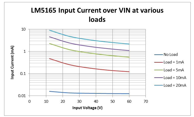
Figure 1 shows the input current data for an LM5165 DC/DC converter over the input voltage and load current ranges.
 Figure 1 Input Current of the LM5165 at
Different Load Currents
Figure 1 Input Current of the LM5165 at
Different Load CurrentsAs you can see, at a 48V input voltage and 10mA load current, the input current consumption from the converter is around 1.3mA. This is almost a one-tenth current reduction compared to a single LDO stage, where a load current of 10mA would require an input current of 10mA.
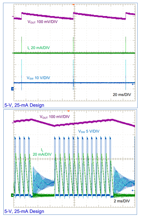
The periodic switching of the converter causes lower current consumption at the input. Figure 2, taken from the LM5165 synchronous buck converter data sheet, shows that at no load the device does not switch continuously; instead, it waits a certain period before it switches again. Figure 2a is at a no-load condition and Figure 2b was taken at a 25mA load current.
 Figure 2 Switching Waveform at No Load
(a); and a 25mA Load (b)
Figure 2 Switching Waveform at No Load
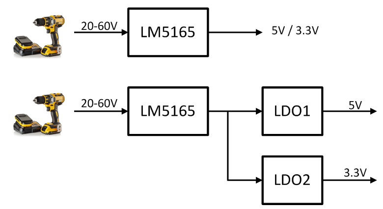
(a); and a 25mA Load (b)The LM5165 has the flexibility for you to create a power design tree for a handheld cordless tool like that shown in Figure 3.
 Figure 3 Example of a High-voltage
Handheld Cordless Tool Battery Power Conversion Diagram
Figure 3 Example of a High-voltage
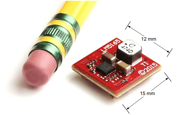
Handheld Cordless Tool Battery Power Conversion DiagramBattery-operated devices sometimes also require a small solution size. Figure 4 shows how the LM5165 evaluation module for a 5V, 25mA output current can fit into a 12mm-by-15mm package.
 Figure 4 LM5165 Evaluation Module Size
Comparison
Figure 4 LM5165 Evaluation Module Size
ComparisonAs you can see, it’s possible to use a low-quiescent-current switcher to boost overall system efficiency for high-voltage conversion. If you still need an LDO for its low-noise advantages, an extra DC/DC converter stage can reduce the input current that will drain from the battery.