SSZT547 february 2019 DRV8350 , DRV8350R , INA240
Imagine that you’re designing the next power stage of a servo, computer numerical control (CNC) or robotics application. In this instance, the power stage is a low-voltage DC-fed three-phase inverter for voltages ranging from 12 VDC to 60 VDC, with power ratings less than 1 kW. This voltage rating covers the range typically used for battery voltages in battery operated motor systems or low voltage DC-fed motor systems. On top of this, your boss says, “By the way, you need to design this to work without extra cooling of the power stage. It has to be as small as possible to fit the target application needs and of course it needs to be low cost.”
No problem, right?
Well, in this case, there is a approachable solution for designing an inverter that meets the demands of this hypothetical – albeit demanding – boss.
So before you start defining the specified power stage, current sensing and protection circuit, it is important to consider a very real and accessible reference design for 48-V/500-W three-phase inverter with smart gate driver servo drives.
This reference design achieves a small form factor using highly integrated ICs that include three half-bridge gate drivers with 100% duty-cycle operation. Selectable source/sink currents from 50 mA to 2 A. VDS sensing enables overcurrent protection which prevents damage to the power stage and motor. The VGS handshake feature protects the power stage against shoot through due to the wrong pulse-width modulation configuration.
| Download the 48-V, 500-W, three-phase inverter with smart gate driver reference design | |

|
Find out why efficiency, protection, and integration are important design factors for compact DC-fed drives up to 60VDC. |
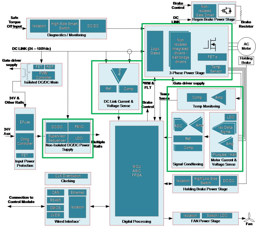
A typical low-voltage DC-fed servo drive power stage can be partitioned like Figure 1, which is based on the DC-fed servo drive power-stage module. The boxes outlined in green are the modules.
 Figure 1 DC-fed servo power
stage
Figure 1 DC-fed servo power
stageThe covered modules of the low-voltage DC-fed servo drive in Figure 1 have a huge impact on system performance and affect the design considerations.
A robust system can be built by adding fault detection to the half-bridge gate drivers for VDS sensing and soft shutdown. These features allow the gate-driver system to detect typical overcurrent or short-circuit events. That is done without adding extra current sensing or hardware circuits to enable dead-time insertion which ensures that the MCU can’t provide a wrong drive signal that can cause damage to either the power stage or the motor due to a shoot through-short circuit.
One consideration is optimizing efficiency to reduce cost for the heat sink and radiated emissions (EMI) versus the switching speed. Implementing these features with 100-V single- or half-bridge field-effect transistor (FET) gate drivers requires additional active and passive components, which increases the bill of materials (BOM) cost and printed circuit board size, while often reducing the flexibility to modify parameters like the strength of the gate drive. When analyzing the system efficiency the current sensing circuit, FETs with low RDS(on) and a low gate charge to enable fast switching, effect the system efficiency performance. Typically system designers want to achieve 99% efficiency of the power stage.
To allow for continuous phase current sensing with minimum losses 1-mΩ inline shunts were used in the reference design. The resistor value was chosen as a compromise between accuracy and efficiency. A major challenge for non-isolated inline amplifiers is the wide common-mode voltage (0V to 80V) used for the system, considering the shunt full-scale voltage is ±30mV in this reference design (designed for ±30Arms). This is a small signal compared to the common-mode voltage of 48V. Therefore, a current-sense amplifier with a large common-mode voltage range and very high DC and AC common mode rejection is required. Due to the low shunt impedance, an amplifier with an additional integrated fixed gain and zero offset further helps reduce system cost while ensuring highly accurate current measurements.
An 100-VDC buck regulator creates an intermediate rail from the DC input to supply the gate driver and point of load. The power stage needs to work at high efficiency to reduce self-heating this is needed to meet the industry ambient temperature of operation which is typically 85°C. With this in mind it means that the IC’s used in the system needs to support even higher temperatures, as the electronics will always have some temperature increase (self-heating).
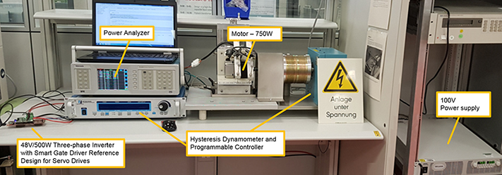
The reference design for servo drives was tested from 0 to 500W output power with a PMSM motor the motor load was controlled with the Dynamometer as shown in Figure 2.
 Figure 2 Test setup of motor drive
power stage
Figure 2 Test setup of motor drive
power stageConclusion
The three-phase inverter reference design shows how to design a compact hardware-protected power stage with low BOM count, in-phase current sensing, fault diagnostic capabilities and high efficiency. The reference design uses the Texas Instruments DRV8350 100-V three-phase smart gate driver with buck regulator and the INA240 80-V, low-/high-side, bidirectional zero-drift current-sense amplifier with enhanced pulse-width modulation rejection, which enables optimization of a low-voltage DC-fed power stage.
Additional Resources
- Learn more about TI smart gate drivers for low-voltage systems.
- Discover more about TI motor drives and integrated gate drivers.
- Read “Field Oriented Control (FOC) Made Easy for Brushless DC (BLDC) Motors Using TI Smart Gate Drivers.”