SSZT517 march 2019 ISO1540 , ISO1541 , ISO7041 , ISO7731 , ISOW7841 , ISOW7842 , SN6501
- 1
-
2
- 3
- 4
- 1. When Is Isolating I2C Necessary?
- 2. Is It Possible to Connect Two Unidirectional Channels on Digital Isolators to Achieve a Bidirectional Channel for I2C Communication?
- 3. What Is the Current Consumption of ISO1540 and ISO1541 Isolated I2 C Devices?
- 4. What Recommended Logic High and Low Input Voltage Levels Can Be Applied to ISO1540 and ISO1541 Isolated I2C Devices?
- 5. Why Is the Logic-low-level Output Voltage, vOL1, Up to 0.8 v on Side1 of ISO1540 And ISO1541 Bidirectional I2C Isolators?
- 6. How Do You Generate Isolated Power for an I2C Isolator?
- What Questions Did We Miss?
- Additional Resources
Become an isolated I2C expert with our design challenges FAQ. These insights are based on frequently asked questions from the TI E2E™ Community about I2C isolators. We hope this information provides actionable details for engineers working to isolate signals and power in their designs.
1. When Is Isolating I2C Necessary?
Isolation prevents DC and unwanted AC between two parts of a system, while still enabling signal and power transfer between each part. Isolation typically protects electrical components or humans from dangerous voltage and current surges; isolation for human safety is called reinforced isolation. I2C has become a popular global standard in many systems; thus, isolated I2C has spread to most high-voltage markets.
Common isolated I2C applications include:
- Microcontroller (MCU)-to-MCU communication in network and server power supplies.
- MCU to analog-to-digital converter communication in automotive battery management systems and medical systems.
- MCU-to-power-sourcing-equipment controller communication in Power over Ethernet systems.
- MCU communication with current-/power-monitoring systems.
2. Is It Possible to Connect Two Unidirectional Channels on Digital Isolators to Achieve a Bidirectional Channel for I2C Communication?
No, connecting two unidirectional channels in opposite directions back to back will not yield a bidirectional channel. If you replace an isolated I2C device with a digital isolator, the digital isolator would latch to a single state and become unresponsive. External components are necessary to implement an isolated I2C bus using digital isolators. For more information on how to implement isolated I2C with a standard digital isolator, see the Analog Design Journal article, “Designing a reinforced isolated I2C bus interface by using digital isolators.” Additionally, this E2E Community Isolation forum thread goes into more detail as to why a digital isolator will latch to a single state when used without external components in a bidirectional I2C application.
3. What Is the Current Consumption of ISO1540 and ISO1541 Isolated I2 C Devices?
Table 6.10 in the ISO154x data sheet lists the current consumption of the ISO1540 and ISO1541 without any pull-up resistors. When you add a pull-up resistor, there will be additional current drawn from the resistors. For example, with a pull-up resistor added to the device of 1 kΩ at SDA2/SCL2 and 10 kΩ at SDA1/SCL1, with VCC1 = VCC2 = 5 V, the additional current consumed by the pull-up resistors will be ~5 mA for SDA1/SCL1 and ~0.5 mA for SDA2/SCL2.
For isolated I2C applications requiring even lower power consumption, the ultra-low-power ISO7041 can replace the ISO7731 device, as described in the Analog Design Journal article mentioned in question No. 2. The ISO70xx power consumption will be an order of magnitude better than ISO77xx devices.
4. What Recommended Logic High and Low Input Voltage Levels Can Be Applied to ISO1540 and ISO1541 Isolated I2C Devices?
Table 1 lists the recommended logic input voltage levels for ISO1540 and ISO1541 devices for Side1 and Side2 inputs.
| Side1 | Side2 |
| VIL1 < 0.5 V | VIL2 < 0.3*VCC2 |
| VIH1 > 0.7*VCC1 | VIH2 > 0.7*VCC2 |
These input voltage levels apply to both the I2C data and clock signals. For more information, see Table 6.3 in the ISO154x data sheet.
5. Why Is the Logic-low-level Output Voltage, vOL1, Up to 0.8 v on Side1 of ISO1540 And ISO1541 Bidirectional I2C Isolators?
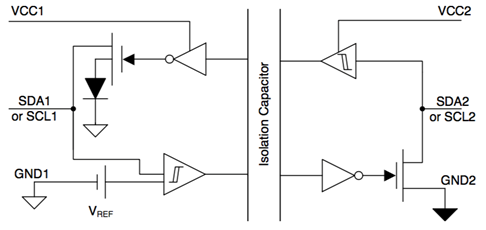
To achieve the bidirectional functionality of an isolated I2C device, the device needs to be designed with two unidirectional channels connected back to back to achieve a single bidirectional channel. Connecting the two unidirectional channels back to back directly would lead to a lockout situation, where both channels are low. To avoid this, a diode at the output of Side1 makes the low output of the output channel on Side1 look like a high for the input channel of Side1. Figure 1 shows the diode placement.
 Figure 1 ISO154x Simplified Schematic
VOL1 will have a voltage of up to 0.8 V because of this diode. When Side2 sees a low on Side2, Side1 will turn on the field-effect transistor, allowing the diode to conduct, generating a nonzero forward voltage. The thresholds in the ISO154x device are carefully designed to make sure that the bidirectional channel operates smoothly – as long as the VOL and VIL specifications fall within the thresholds of the ISO154x device shown in Table 6.9 of the ISO154x data sheet. This approach has been a common practice in the industry for achieving bidirectional I2C function. A nonzero voltage of logic level low will still be compatible with I2C specifications.
Note that this only applies to VOL1. Since Side2 of the device does not require a diode, the VOL2 will be 0.4 V max, which is common in most digital isolators.
6. How Do You Generate Isolated Power for an I2C Isolator?
There are several options to generate isolated power for an I2C isolator; the best solution depends on the specific application needs.
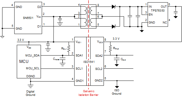
One option is to use a transformer driver like the SN6501, which operates in a push-pull configuration with a transformer and optional rectifying low-dropout regulator on the secondary side (Figure 2). The SN6501 is capable of delivering as much as 1.5 W to provide isolated power. This device has the flexibility for use in almost all applications because the transformer and turns ratio can provide the necessary isolation rating and output voltage for the power supply. You can use the SN6505 instead of the SN6501 for as much as 5 W of output power if you need isolated power for additional devices. The SN6505 also has extra protection features such as overload and short circuit, thermal shutdown, soft start, and slew-rate control, enabling a robust solution.
 Figure 2 Isolated I2C Solution for Signal and Power with ISO1541
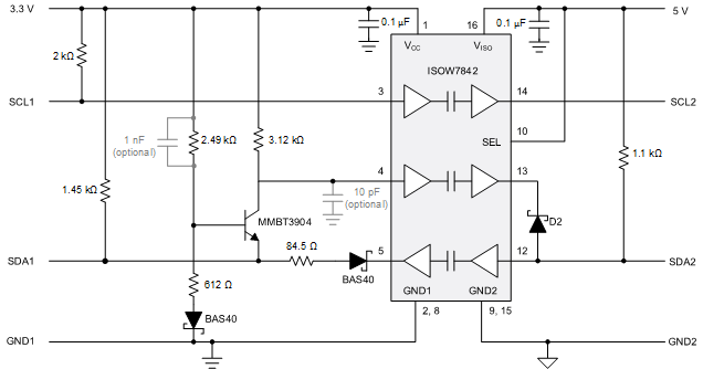
Another option for space-constrained applications is the ISOW78xx family of devices, which provides signal and power isolation in a small-outline integrated circuit 16-pin package. The ISOW7842 can also be combined with external components. Figure 3 shows an example solution for a system with bidirectional data and a unidirectional clock, which when modified with a few extra components can support bidirectional data and clock signals.
 Figure 3 Isolated I2C Solution for Signal and Power with ISOW7842
For more information about the advantages and drawbacks of each isolated power option, see “How to Isolate Signal and Power for Isolated I2C.”
What Questions Did We Miss?
If you’re looking for more information about I2C isolators or have a question you would like to see added to this list, leave a comment below and help keep the conversation going.