SSZT500 April 2023 THVD1419 , THVD1424 , THVD1429 , THVD1450 , THVD1500 , THVD1550 , THVD2450
- 1
-
2
- 3
- 1. When Do You Need Termination on Your RS-485 Bus, and How Do You Terminate Properly?
- 2. What Is Fail-safe Biasing, and How Do You Implement It?
- 3. How Do You Calculate the Maximum Number of Nodes on an RS-485 Bus?
- 4. How Do You Know When You Need to Add a Ground Wire between Nodes?
- 5. What’s the Length vs. Speed Recommendation for RS-485?
- 6. How Do You Estimate the Power Dissipation of RS-485?
- 7. How Do You Protect Your RS-485 Interface from Electrostatic Discharge (ESD)?
- 8. How Do You Know If You Need an External TVS Diode?
- 9. How Do You Protect against Short-circuits to Higher Voltages?
In need of a refresher on RS-485 transceiver design? This blog post features insights based on frequently asked questions within the TI E2E™ Community and is a helpful resource for anyone looking to learn more about this established communications standard.
For information specific to isolated RS-485 transceivers, check out that FAQ post, “Top 7 questions about isolated RS-485 transceivers.”
1. When Do You Need Termination on Your RS-485 Bus, and How Do You Terminate Properly?
RS-485 bus termination is useful in many applications, as this implementation helps improve signal integrity and reduces communication issues. “Termination” means to match the characteristic impedance of the cabling to the termination network, enabling the receiver at the end of the bus to see the maximum signal power. An unterminated or improperly terminated bus will introduce a mismatch, creating reflections at the end of the network, which can degrade overall signal integrity.
In situations where the two-way loop time of the network is much greater than the signal bit time, termination is not necessary, as the reflections will lose energy each time they reach the end of the network. But for applications where the bit time is not substantially longer than the cable loop time, termination is crucial in order to minimize reflections.
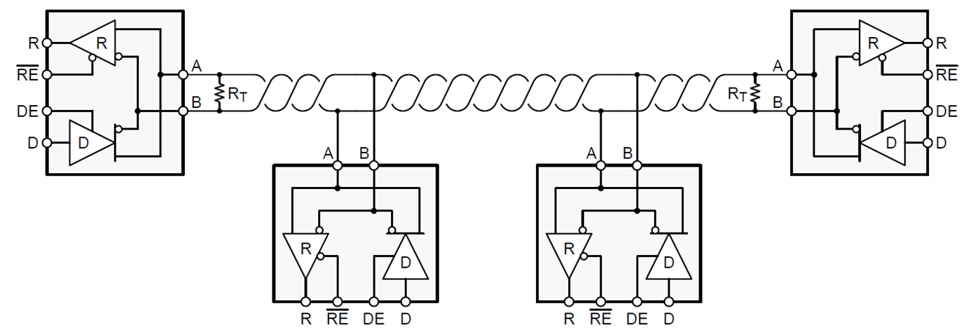
The most basic termination is known as parallel termination and consists of a single resistor, as shown in Figure 1. The RS-485 standard requires 120 Ω as the nominal characteristic impedance, so termination resistors should have RT = 120 Ω as the default value. Read the blog post, “RS-485 basics: When termination is necessary, and how to do it properly.”
 Figure 1 RS-485 Bus with Parallel
Termination
Figure 1 RS-485 Bus with Parallel
TerminationThe THVD1424 transceiver is a flexible RS-485 transceiver with integrated 120 Ω termination resistor across driver and receiver bus pins. The termination resistor can be switched ON/ OFF by dedicated pins TERM_TX and TERM_RX. It provides system designers with the flexibility to use the same device for half or full duplex network and at all node locations (middle nodes or end nodes).
For more information on this topic and device features, please refer to the technical white paper “Reduce System Design Time and Cost with Flexible RS-485 Transceivers.”
2. What Is Fail-safe Biasing, and How Do You Implement It?
Fail-safe biasing is a way for you to ensure that your RS-485 receivers do not fall in an indeterminate state for differential input voltages. The Electronic Industries Alliance (EIA)-485 standard states that the input thresholds of an RS-485 are logic high for differential voltages ≥+200mV and logic low for differential voltages ≤-200mV, which leaves a 400-mV indeterminate state between the high and low thresholds.
You can implement fail-safe biasing in two ways:
- Select transceivers that have built-in fail-safe input thresholds in the receiver.
- Add external resistors to create an external bias on the idle bus.
Both methods will ensure a logic-high state on the bus. Read the blog post, “RS-485 basics: two ways to fail-safe bias your network.
3. How Do You Calculate the Maximum Number of Nodes on an RS-485 Bus?
RS-485 is a multipoint differential bus, meaning that all of the nodes on the bus share one common transmission medium. As the total number of nodes increases, the loading on each driver will increase as well.
The Telecommunications Industry Association (TIA)/EIA-485 standard created a hypothetical unit load (UL) to help calculate the maximum number of nodes on an RS-485 bus. The standard states that a driver must be able to drive at least a 1.5-V differential signal across a maximum of 32 unit loads in parallel with two 120-Ω termination resistances at opposite ends of the bus.
Equation 1 expresses the worst-case ratio of the input voltage divided by leakage current to calculate the input resistance. After you’ve established the input resistance of the node, you can calculate the maximum number of nodes on an RS-485 bus with Equation 2:
Input Resistance = Max (VIN/Ileakage) (1)
No. of Nodes = 32/Input Resistance (2)
4. How Do You Know When You Need to Add a Ground Wire between Nodes?
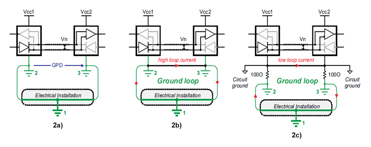
 Figure 2 Remote Node Configurations: Separate Grounds (a); Directly Connected Remote Grounds (b); Separation of Device Ground and Local System Grounds (c)
Figure 2 shows remote nodes that are likely to draw their power from different sections of an electrical installation. Any modification to the installation, such as during maintenance work, can increase the GPDs to the extent that the receiver’s input common-mode range is exceeded. Thus, a data link working today might stop operating in the future.
The direct connection of remote grounds through ground wire is also not recommended (b), as direct connection causes large ground loop currents to couple into the data lines as common-mode noise.
To enable direct connection of remote grounds, the RS-485 standard recommends the separation of device ground and local system ground via the insertion of resistors (c). Although this approach reduces the loop current, the existence of a large ground loop keeps the data link sensitive to noise generated somewhere else along the loop. Thus, a robust data link has not yet been established.
The best approach to tolerate GPDs up to several kilovolts across a robust RS-485 data link and over long distances is to galvanically isolate the signal and supply lines of the bus transceiver from its local signal and supply sources. In this case, supply isolators (such as isolated DC/DC converters) and signal isolators (such as digital capacitive isolators) prevent current flow between remote system grounds and avoid the creation of current loops.
5. What’s the Length vs. Speed Recommendation for RS-485?
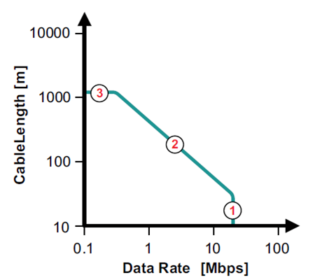
The maximum bus length is limited by the transmission line losses and the signal jitter at a given data rate. Because data reliability sharply decreases for jitter of 10% or more of the baud period, Figure 3 shows the cable length vs. data-rate characteristic of a conventional RS-485 cable for a 10% signal jitter.
 Figure 3 Cable Length vs. Data-rate
Recommendations
Figure 3 Cable Length vs. Data-rate
RecommendationsOn Figure 3, the circle labeled No. 1 represents the area of high data rates over a short cable length. Here, you can neglect the losses of the transmission line; the data rate is mainly determined by the driver’s rise time. Although the standard recommends 10 Mbps, today’s fast interface circuits can operate at data rates as high as 50 Mbps.
The red No. 2 on Figure 3 represents the transition from short to long data lines. You have to take into account the losses of the longer transmission lines. Thus, with increasing cable length, the data rate must be reduced. A rule of thumb states that the product of the line length [m] times the data rate [bps] should be 108.
The red No. 3 represents the lower-frequency range, where the interaction between the cable series resistance and the end-of-line termination results in attenuation of the signal. At a certain point, the amplitude of the signal becomes smaller than what the receiver can properly detect (that is, it does not exceed the VIT threshold).
The THVD1424 transceiver has SLR (slew rate control) pin which enables the system designers to use the same device for slow speed (maximum 500 kbps) and fast speed (maximum 20 Mbps) applications.
6. How Do You Estimate the Power Dissipation of RS-485?
To calculate the power dissipation, you can divide the power into several parts. When the device powers on with no external load, the power consumption is used for the integrated circuit itself. If you add loads at the output pins, the power of driving the load will be drawn from the device. Since RS-485 has differential signaling, the load is usually added between the A and B pins.
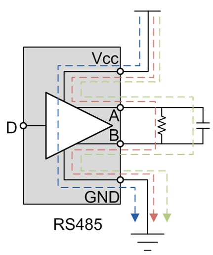
In Figure 4, the blue trace, PDic, is the power the device consumes. For low data rates, the power dissipation mostly comes from the resistive load (the red trace), PDdc. For high data rates, the power dissipation from the capacitive load needs to be accounted for (the green trace), PDac.
 Figure 4 Power Dissipation Sections for Calculation
Equation 3 calculates the total power dissipation as:
PDtotal = PDic + PDdc + PDac (3)
To calculate the total power dissipation, you must first calculate each portion of the power. The device power consumption is described by Equation 4, where the quiescent supply current, Icc, is specified in the data sheet:
PDic = Vcc*Icc (4)
If you put a resistive load on the bus, the driver generates a voltage (Vod) on it, as illustrated in Equations 5 and 6, where C is the parasitic capacitance, which includes the capacitance of the transceiver, the capacitance of the load and the trace capacitance. The data frequency, f, is also included in the calculation.
PDdc = Vcc*I – I2*R = (Vcc – I*R)*I (5)
PDac = 2*2C*f*Vcc*Vod (6)
Read the blog post, “How to calculate the power dissipation of high-speed RS-485 transceivers.”
7. How Do You Protect Your RS-485 Interface from Electrostatic Discharge (ESD)?
There are several types of ESD protection, including human body model, International Electrotechnical Commission (IEC) contact discharge and IEC air-gap discharge. If a transceiver has integrated IEC ESD (such as TI’s THVD1450 or THVD1500), then it requires no external components to protect the RS-485 interface from ESD at the level at which the transceiver is specified.
For example, without any external components, the THVD1450 can support 18-kV IEC 61000-4-2 contact discharge. However, many devices in the market do not have this integration and would require external transient voltage suppression (TVS) diodes. Read the blog post, “How to choose a TVS diode for RS-232, RS-485 and CAN based on voltage ratings.”
8. How Do You Know If You Need an External TVS Diode?
Industrial networks must operate reliably in harsh environments. Electrical overstress transients caused by ESD, the switching of inductive loads or a lightning strike will corrupt data transmission and damage bus transceivers – unless you take effective measures to diminish transient impact.
TI devices have been tested according to these standards:
- The ESD immunity test, IEC 61000-4-2, simulates the electrostatic discharge of an operator directly onto an adjacent electronic component. The THVD1500 and THVD1450 were tested to this standard.
- The electrical fast transient (EFT) or burst immunity test, IEC 61000-4-4, simulates the everyday switching transients caused by the interruption of inductive loads, relay contact bounce, etc. The THVD1450 and THVD1550 were tested to this standard.
- Surge immunity test IEC 61000-4-5, the most severe transient immunity test in terms of current and duration, is approximately 1,000 times longer than the ESD and EFT tests. The THVD1429 and THVD1419 were tested to this standard.
TI’s latest RS-485 transceivers from the THVD family integrate various levels of protection according to these standards and do not require additional external protection. The levels of protection are specified in the device’s data sheet.
9. How Do You Protect against Short-circuits to Higher Voltages?
In many RS-485 applications, there exists a risk of inadvertently connecting the communication lines to power supply lines. This risk is particularly high in field-installed systems such as HVAC systems, lighting controls or other building automation applications. In these cases, it is important to ensure damage does not occur to the RS-485 transceiver in order to avoid costly field returns and re-installation.
While clamping components like TVS diodes are capable of limiting the maximum voltage seen by a transceiver during a transient event, they are typically not able to protect against longer-duration stresses such as DC shorts. To protect against these, some series current-limiting element is needed. A typical approach involves using a positive temperature coefficient (PTC) resistor, which has a low resistance under nominal conditions but a high resistance during fault conditions when a large current flows through it (for example, into a clamping device like a TVS). An example of such an implementation using the THVD1500 transceiver can be seen in the TI reference design, “Protecting RS-485 transceivers from sustained high voltage/electrical over-stress reference design.”
However, use of these additional series current-limiting and shunt voltage-clamping components can be costly and take up valuable PCB space. In most cases, then, a more optimized approach is to use a transceiver capable of tolerating these high fault voltages without requiring external protection. An example would be the THVD2450, which is rated to withstand DC short-circuits up to +/- 70 V.
Anything we missed? Let us know in the comments, and we will send feedback to help you overcome your RS-485 design challenges.