SSZT470 june 2019
When designing a power stage for motor control, you can drive down the total system cost if you make special considerations regarding efficiency. This includes optimizing the field-effect transistor, switch node and control algorithms. During design, you will need to protect the system against an over temperature condition. Over temperature means that if the system gets to a certain temperature level, the components on the printed circuit board are outside their specification ranges. This can damage the components and cause the drive system to malfunction.
Temperature sensors monitor and protect power-stage components to keep the drive system within the safe operating area (SOA). A SOA is a defined operating temperature range for the system at a specific apparent load or root-mean-square (RMS) current in a phase, which the drive can support without extra cooling abilities. The temperature range for industrial equipment is typically an ambient temperature of -40°C to 85°C.
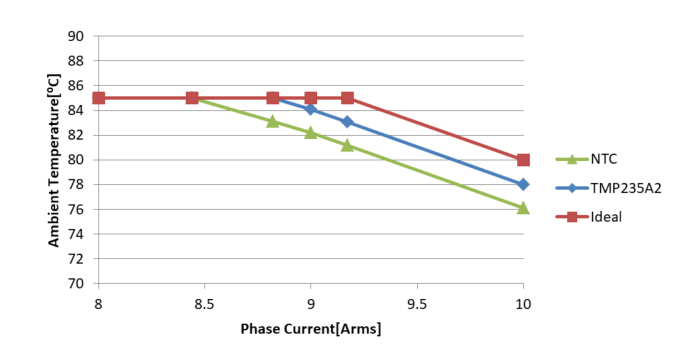
TI’s 48V/500W Three-Phase Inverter with Smart Gate Driver Reference Design for Servo Drives was used to generate an SOA curve. The “ideal” curve of the SOA, shown in Figure 1. The curve is defined based on results from thermal camera testing and an efficiency measurement at 10 ARMS. With an assumed zero temperature error, this curve is used as a reference against a negative temperature coefficient (NTC) thermistor and the TMP235A2 sensors. The difference in the SOA is a result of the temperature error of the sensors and indicates the need for a safety margin in order to ensure operation within the SOA of the drive.
| 48V/500W Three-phase Inverter with Smart Gate Driver Reference Design for Servo Drives | |

|
 Download the design
|
 Figure 1 SOA Difference Due to Sensor
Temperature Error Compensation
Figure 1 SOA Difference Due to Sensor
Temperature Error CompensationHow does the temperature error degradation of SOA affect system performance?
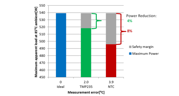
In Figure 1 it can been seen what effect the temperature error has in regards to RMS current at ambient temperature, here is it assumed the NTC has an error of 3.9°C and the TMP235A2 has an error of 2.0°C, this assumption is described in detail in part 2 of this blog. Using the SOA curve on the maximum phase current with regards to ambient temperature, it is possible to define the maximum phase current possible before cooling is needed. Now this maximum phase current is used to calculate the power degradation of the power stage given a specific temperature sensor error. Figure 2 is based on calculations found in the three-phase inverter reference design.
 Figure 2 Usable Apparent Load at 85°C
Using Different Temperature Sensors
Figure 2 Usable Apparent Load at 85°C
Using Different Temperature SensorsYou can see that the power stage can support 539 W – if it was possible to measure the temperature without error. Now, because of the temperature error of the sensor, you’ll need to add a safety margin. This safety margin means that the power stage needs to be degraded by 4% or 8% of the potential power usage of a servo drive power stage module system. If the power stage needs to support 500 W (which is clearly possible as seen in Figure 1) but you choose to use a NTC, you would need to add additional cooling to the system to support the system’s full temperature range, or redesign the system for higher efficiency the 48V/500W Three-phase Inverter with Smart Gate Driver Reference Design for Servo Drives is already running at higher 99% efficiency on the power stage. This increases the design time and cost.
In the next installment of this series, I will explain considerations, theories and tools used to generate the figures in this installment, and explain why it is worth it to spend time deciding which temperature sensor to use.