SSZT405 september 2019 TPS63802 , TPS63805 , TPS63806 , TPS63810
Most applications or subcircuits require a constant voltage supply within a certain voltage tolerance window in order to operate properly. Battery-driven applications such as wireless sensors and personal handheld devices need voltage conversion to generate the required output voltages while the battery discharges and reduces its voltage. Applications supplied by a fixed rail such as optical modules, wired sensors, or active cables or dongles might also need voltage conversion if the available rails do not fit the required input voltage, or if the voltage variation exceeds the required tolerance window.
In this article, I will show how a buck-boost converter might be a good solution for voltage conversion, and whether it might even be a universal tool for any type of DC/DC voltage conversion.
When to use a buck-boost converter
Typically, if the available supply voltage for a circuit or subcircuit is lower than the required voltage, a boost (step-up) converter efficiently converts DC voltages to a higher voltage level. If the available supply voltage is higher than the required voltage, a buck (step-down) converter performs the voltage conversion.
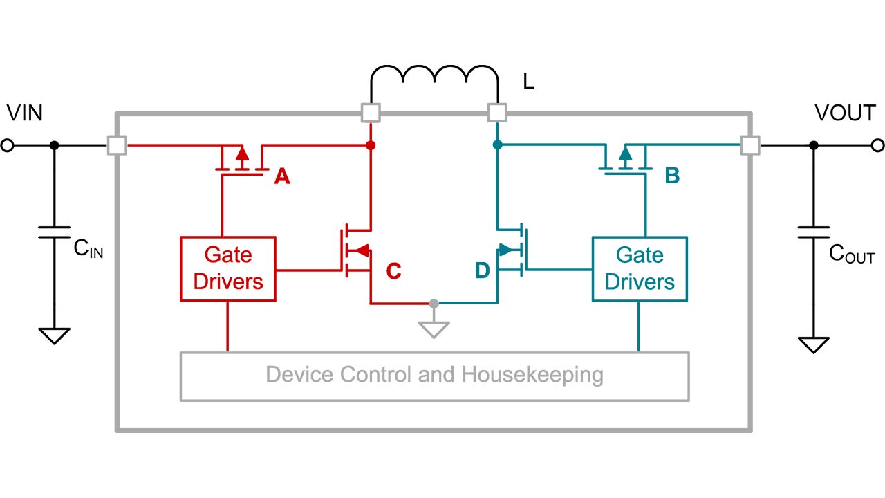
To be able to accept supply voltage ranges that are both higher and lower than the required output voltage, you need a buck-boost converter. A buck-boost converter is a hybrid of a buck and a boost converter, which becomes clearer when looking at its block diagram, shown in Figure 1.
 Figure 1 Buck-boost converter block diagram
By merging the architecture of a buck converter (shown in red in Figure 1) with the architecture of a boost converter (shown in green in Figure 1), a buck-boost converter can both step up and step down the output voltage. Depending on the actual input voltage and programmed output voltage, the control loop determines whether the device needs to operate in buck or boost mode.
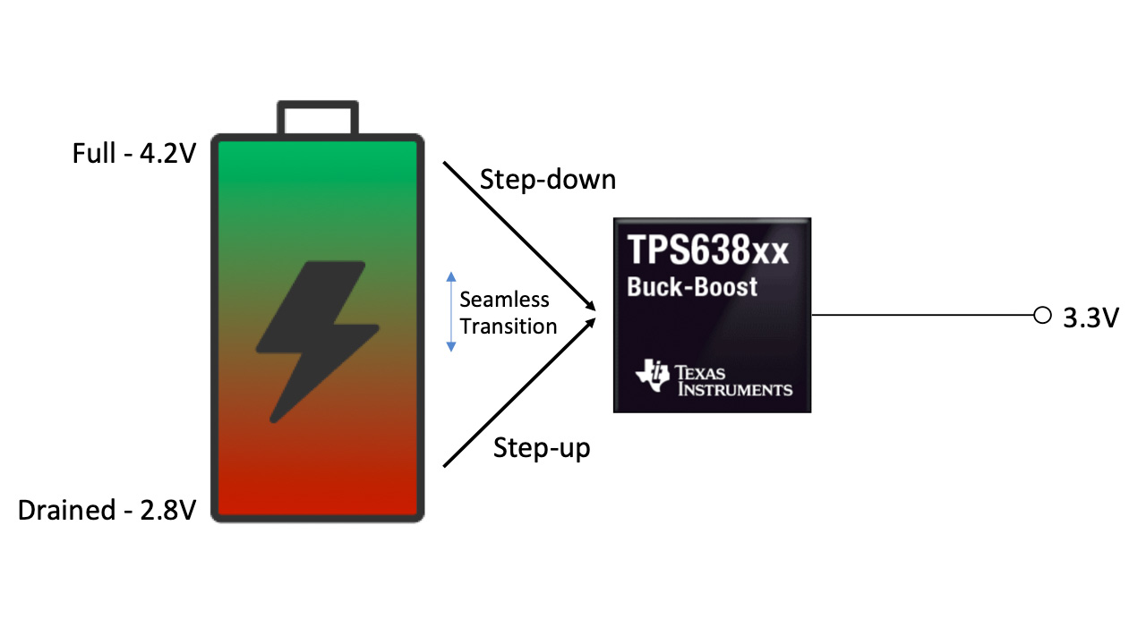
As an example, let’s assume that you needed to get 3.3 V out of a lithium-ion battery with a typical voltage range of 4.2 V to 2.8 V. If you used a buck converter, the battery cut-off voltage would need to be greater than 3.3 V, with the drawback of leaving energy stored in the battery unused. However, a buck-boost converter can help squeeze all of the energy out of the battery because it can also drain the energy stored when the input voltage is equal to or lower than 3.3 V, as visualized in Figure 2.
 Figure 2 A buck-boost converter drains the battery completely
Using buck-boost converters as voltage stabilizers
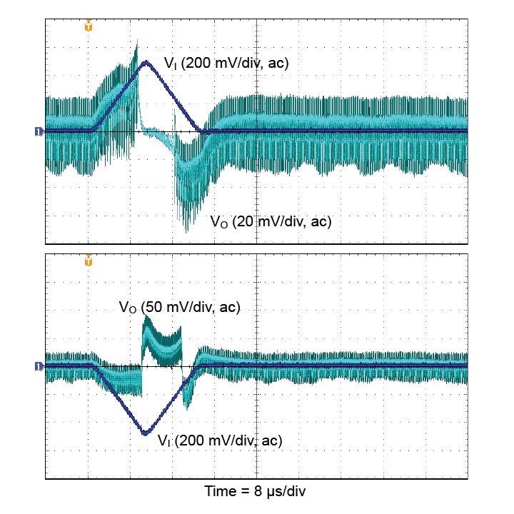
A second common use for a buck-boost converter is as a voltage stabilizer. You’ll need a voltage-stabilizing buck-boost converter if a supply rail has variations (such as 3.3 V with ±10% variation) while the load requires a more precisely regulated voltage (such as 3.3 V with ±5% tolerance). A more tightly regulated voltage could be required if components are sensitive to the supply voltage (such as transimpedance amplifiers in optical modules); if other DC/DC pre-regulators are not regulating tightly enough in industrial applications; or if other components such as e-fuses, load switches or long cables in the power path add voltage variation as a function of the current. A boost or buck converter alone could not solve this problem – a buck-boost converter, however, would be able to regulate the varying input voltage to the required, tighter limits. Figure 3 shows the TPS63802 responding to a fast ±0.5 V/10 µs line transient with significantly less than ±0.1V output voltage under-/overshoot.
 Figure 3 Line Transient Response for the TPS63802 at VI = VO = 3.3V, ΔVI = ±0.5V
Additional applications for buck-boost converters
There are additional reasons to choose a buck-boost converter over a buck or boost converter alone. One of those reasons includes power ORing. Imagine a device such as a baby monitor powered by a 5-V USB wall adapter or two AA primary cells ranging from 3 V (when new) down to 1.6 V (when the batteries are drained). Only a buck-boost converter can accept a wide input voltage range from 5 V (wall adapter) down to 1.6 V (depleted battery while the wall adapter is not connected) and still generate a 3.3-V rail for the system. Apart from the buck-boost converter, you would only need two external diodes to avoid cross-currents from the wall adapter to the battery and to switch seamlessly to the battery if the wall adapter gets unplugged.
Buck-boost converter limitations
When the input voltage is close to the output voltage, the internal control loops of the buck-boost converter are often designed to toggle constantly between buck and boost mode. This works acceptably, but has drawbacks: mode toggling might show a varying switching frequency, a higher output voltage ripple and more electromagnetic interference (EMI). As a secondary effect, efficiency could dip slightly at this point.
To avoid the effects of mode toggling, look for devices with a dedicated buck-boost mode that keeps the output voltage ripple low. One example is TI’s new TPS638xx family of buck-boost converters, where a dedicated buck-boost mode and hysteresis avoid toggling with an easy-to-filter noise spectrum and lower EMI.
Can a buck-boost device handle all types of voltage conversion?
Since a buck-boost converter “contains” a buck and a boost converter, you could use it for any DC/DC voltage conversion – so from that perspective, the answer is yes. But there are more details to consider. Table 1 provides an overview of given input voltage ranges vs. the required output voltage, and if a buck-, boost- or buck-boost converter is a good solution.
| Input/output voltage | Boost converter | Buck converter | Buck-boost converter |
|---|---|---|---|
| VIN always higher than VOUT | Does not work | Ideal topology | Works, but possible drawbacks in efficiency (one additional integrated transistor with on-resistance present in the conducting path), solution size (more silicon area needed) and quiescent current consumption |
| VIN always lower than VOUT | Ideal topology, but needs a specific setup for disconnecting the battery from the load when disabled | Does not work | |
| VIN higher or lower than VOUT | Does not work | Does not work | Ideal topology |
| Boost and buck converter in series: works, but drawbacks in efficiency, solution size, passive component size and costs | |||
Let’s return to the original question serving as the title of this article: Is there a universal tool for DC/DC voltage conversion? Not exactly. Analog designers working on high-volume products will prefer the performance optimization of a dedicated boost or buck converter when a buck-boost converter is not required. However, designers working on small-volume products may consider that some trade-offs are worth the convenience.
Using a buck-boost universally (to buck-boost, boost and buck) could provide these benefits:
- Scaling across projects, to save time and mitigate design risks.
- Reducing the number of different DC/DC converters to a narrow list of easy-to-use buck-boost converters.
- Streamlining procurement, with a less complex inventory, larger volumes for price leveraging and supply stability.
- Benefitting from the fact that a buck-boost disconnects the load from the supply during shutdown, while other topologies might need an additional load switch.
Additional resources
- Watch this video series with TI’s Bernd Geck: part 1 is about buck converters, part 2 is about boost converters and part 3 is about how a buck-boost converter works.
- See how to select a DC/DC converter for maximum battery life in pulsed-load applications.
- Learn how to use a non-inverting buck-boost converter for voltage stabilization.
- Find out how a precise threshold enable pin helps to prevent battery overdischarge.
- Start designing with TI’s new buck-boost converters using WEBENCH® POWER DESIGNER.